So, this is about using piezoelectric element to trigger logical events on the processor.
Note this is different form just hooking up a piezo element to an ADC pin, and sampling. This needs to give digital signals -it's going to be the wake source.
In this implementation the scales should be triggered by a light tap.
So a simple test is done - an oscilloscope connected to the piezo (conveniently as a 1 Mohm load), set to peak detect mode, and then the piezo tapped.
While I can tap sufficient to give +-2.5V, it's hard, and not very reliable. A reasonable level is more like 1V for light tapping.
So, some amplification is needed - the first port of call is to look at the existing circuit. This clearly worked, and felt 'right':
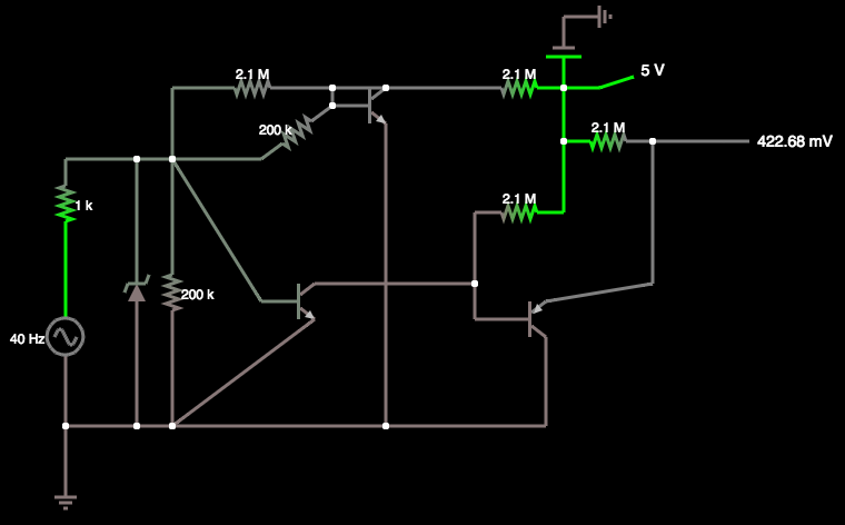
However, it's a bit over complex. Yes, the top transistor was indeed set up like that.
So I simplified - using the same components for the front end.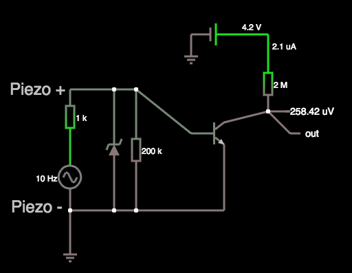
As can be seen by the dubious Falstad simulation, idle current draw when active is only a couple of microamps. When the piezo is at zero, the idle draw is near zero (0.1 pA apparently). The value of the 200k resistor can be tweaked to affect sensitivity to tapping.
The zener diode is there (at 4.7V) to protect the transistor from emitter-base being above 5v, as per the datasheet.
The output now is HIGH when the piezo is still, and oscillates between HIGH and LOW as the piezo flexes and rings.
Next, to breadboard and test it waking an AVR from sleep!
Discussions
Become a Hackaday.io Member
Create an account to leave a comment. Already have an account? Log In.