 Jonathan Buchanan
So, I got the right sized components for the board. I soldered them all up, and it looked like a perfect, elegant, professionally designed PCB.
I actually delayed the testing for a few days because I was so scared it wouldn't work, but eventually I turned on the ADC, plugged in a strip, and inserted a blood sample. Here's the first graph from the PCB.
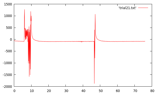
Well. Not exactly what I'd hoped for. Don't panic yet though, this looks like a familiar problem. The very first time I tested the breadboard, I got extremely similar graphs, and, sure enough, I had left the ground off pin #11, just like I did on the breadboard.
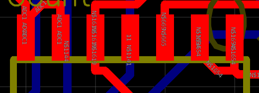
On the circuit designer, I saw this blue wire (actually on the underside of the board) running directly through the middle of pin #11 and assumed it was already connected.
So I soldered a jumper to the nearest ground, and tested it again.
Still not what I'd hoped for, though still familiar. This time though, the familiarity was a red herring, so I won't include the graph of trial 13 on the breadboard which had a similar look.
I'll spare you too many details, but suffice to say the reason this post took so long is that it took me three weeks to find the problem.
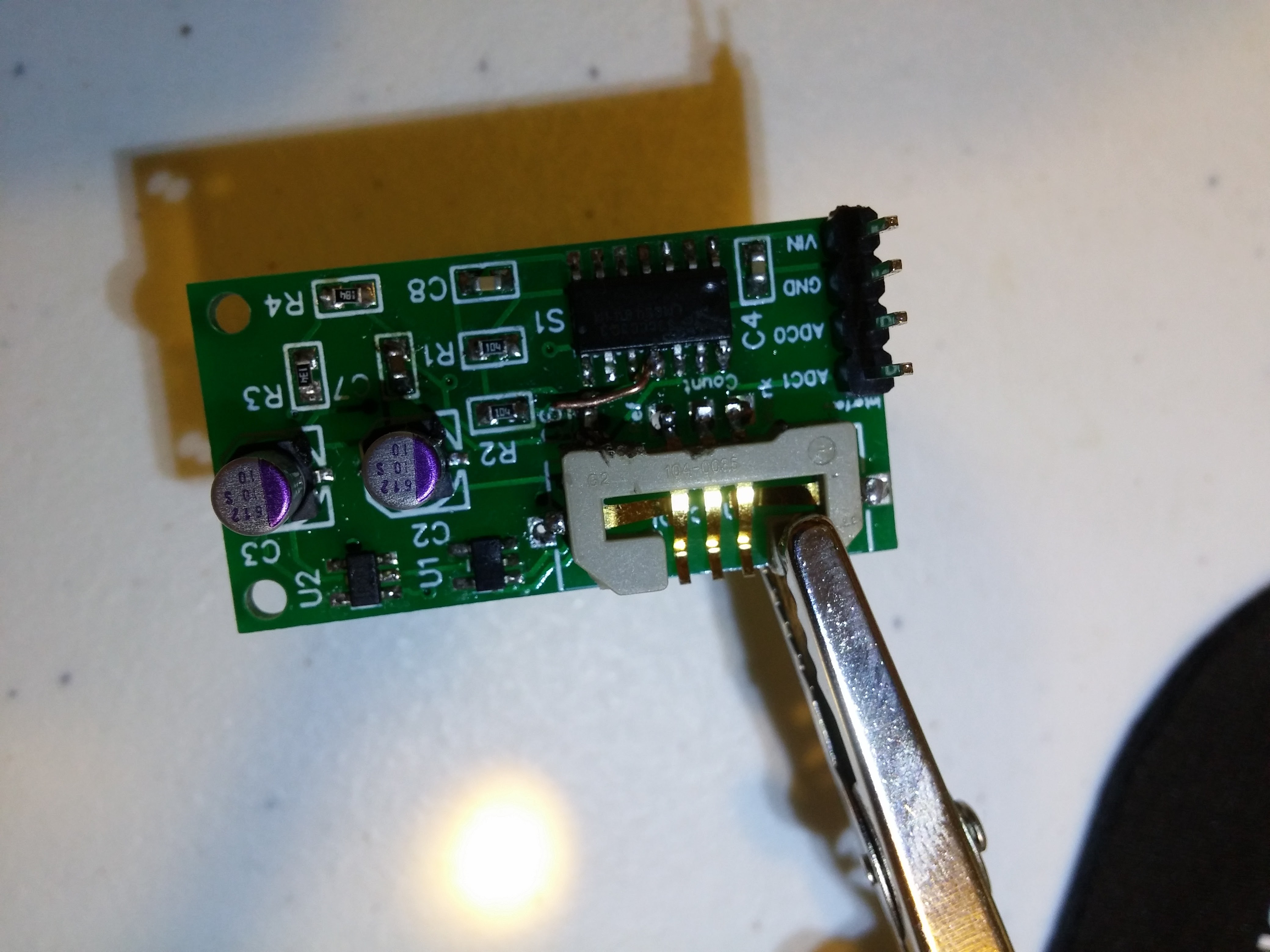
Here is a picture of part of the debugging process.
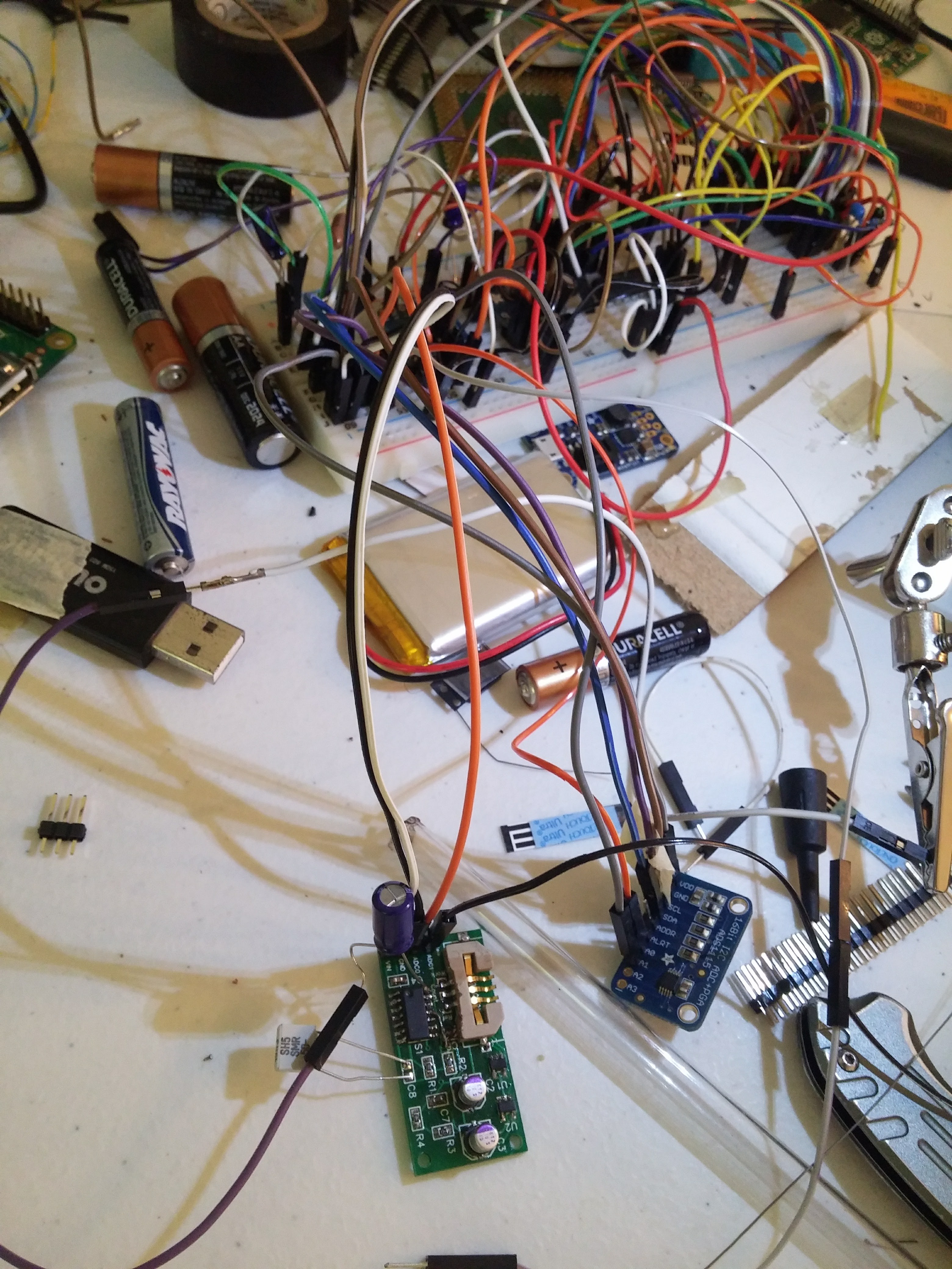
Note the breadboard capacitors soldered to the top of the PCB.
During this time, I learned several valuable things, including:
- the rules of electronics are definitely random, no matter what anybody says
- touching wires with your hands connected to sensitive instruments generates noise (even through insulation)
- it's always a connection problem
- I hate debugging things with random rules
Eventually, after replacing components, checking solder joints, testing voltages and resistances, simulating circuits, and reading ADCs, I discovered the problem lay in the connection between the strip connector and its sockets when I soldered it up externally.
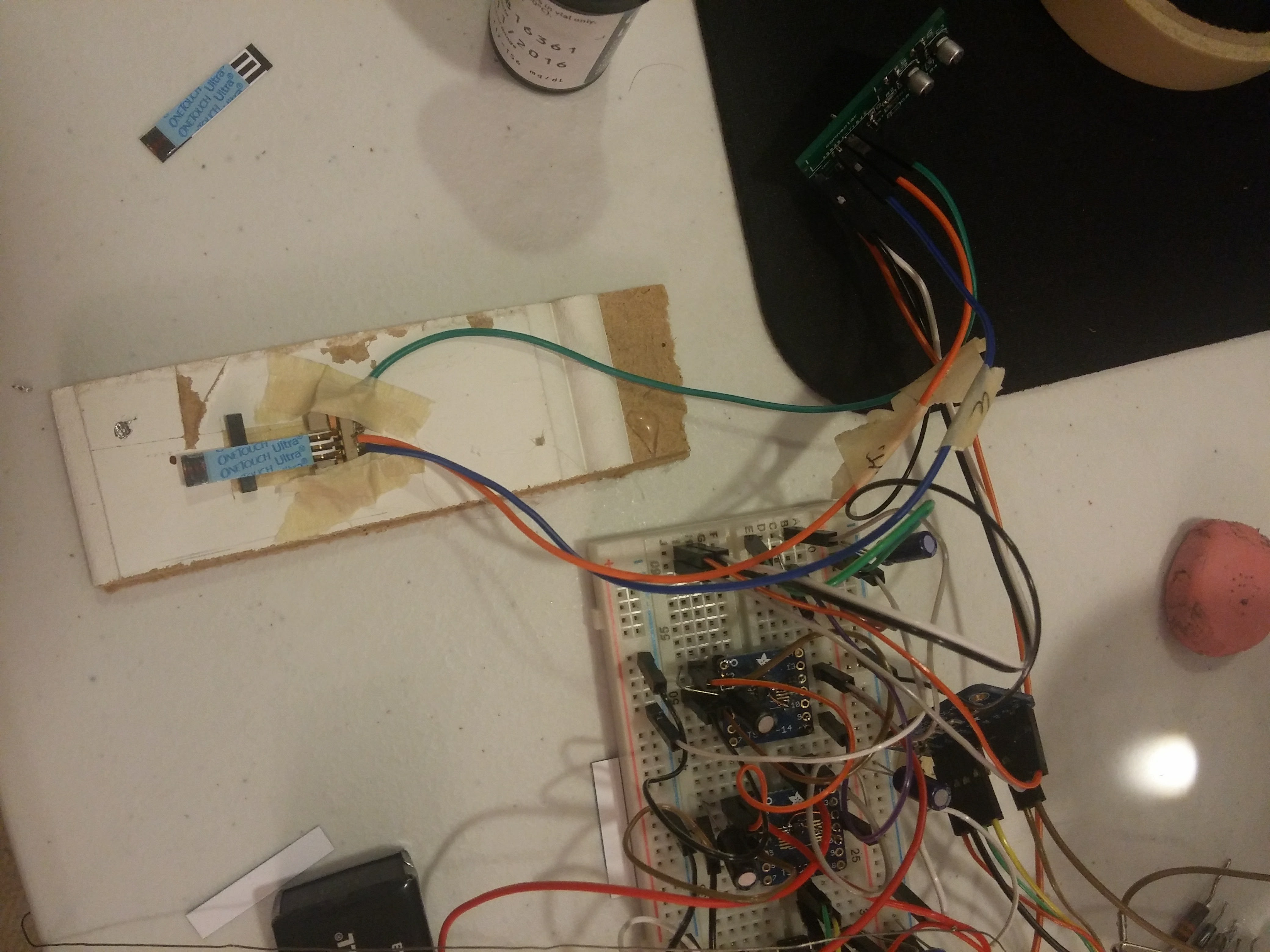
Here, actually both the breadboard meter (bottom) and the PCB meter (top right) are connected to the ADC (bottom right) on separate channels so I could compare the ADC's readings.
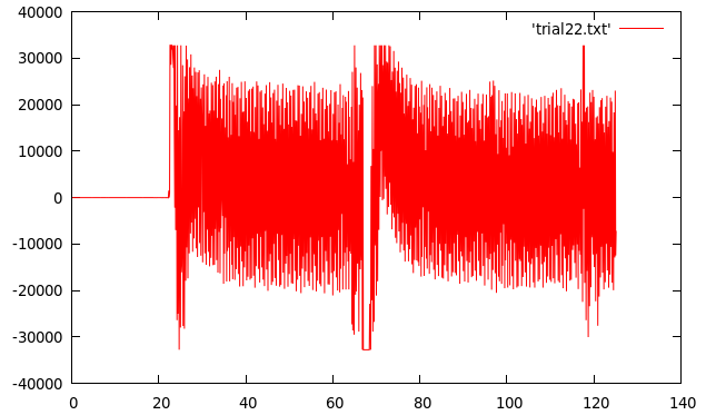
After noticing that the noise read by the ADC was many times lower with the strip connector connected differently, I decided to test it again.
This graph, produced from the PCB meter, shows a curve much more similar to that which the breadboard generated earlier.
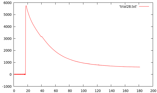
I haven't finished calibrating to make sure the PCB is satisfactorily accurate yet, but I'm optimistic based on the smoothness of that curve.
I've been working on the software side of things, and I will probably post either an update about that, or my process in designing a case for all this next.
Discussions
Become a Hackaday.io Member
Create an account to leave a comment. Already have an account? Log In.