 fl@C@
fl@C@

Note: This log entry is a living document. I'll be updating this post to reflect the current configuration as time goes on.. There will also be a log at the end of the post noting modifications to the log, etc..
UPDATED-----> 09.23.2014

Ok.. It's been a lot of tweaking, and refining... A lot of going over the design, fixing issues and overcoming problems.. But I have reached a pretty good point with the spectrometer design.. I managed to design this part of the system so it can be used completely independently from the rest of the raman setup.. You can print this portion, install the optics, setup the fairly simple electronics, configure the software, make some minor adjustments to the optics so they're properly aligned, hook it up to a PC (or the ramanPi) and get some work done!
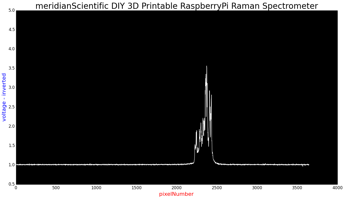
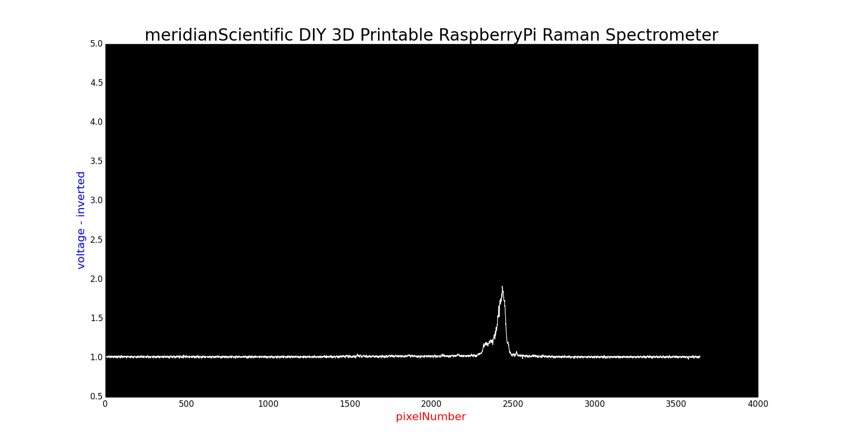
This spectrometer should be about on par with what you'd get from an ocean optics commercial product... Well, at least as good as one could expect to get.. I might experiment a bit with better options than razor blades for the entrance slit.. But really, the diffraction grating is pretty much on par, the CCD is the same model... we should be getting some great results... I need to calibrate mine with a known light source... I have a neon ampoule, and a mercury vapor lamp...I'll be trying those out pretty soon.. In the mean time, I did a quick sample with a 532nm laser.... Here's the result from that...
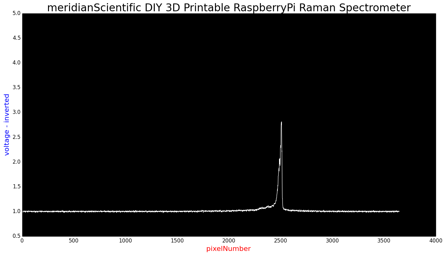
I'd call that pretty clean considering it is my first try... and it's a cheap eBay handheld laser pointer... Unfortunately, we can't use that to calibrate the spectrometer...
HOW TO BUILD A SPECTROMETER - PART 1
I wanted to make this post a sort of how to for assembling the spectrometer... as much as I can anyway... So, here's a quick guide...!
We start by loading up the files to print the plastic parts...
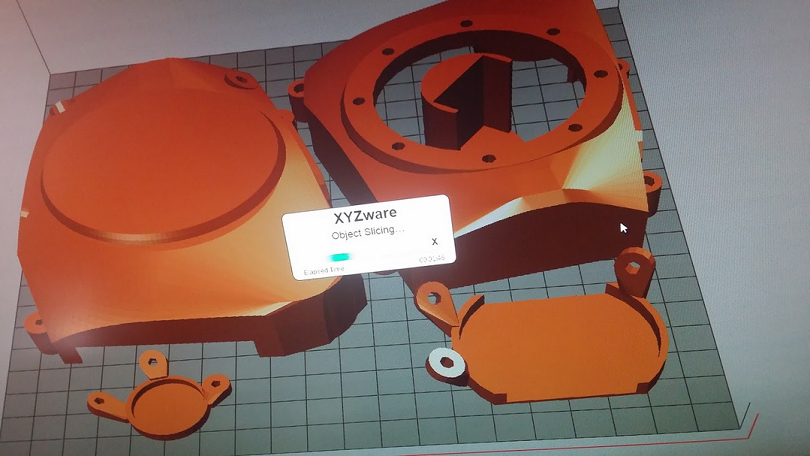
Set up the printer and start printing.... Wait a good 12-18 hours....

Keep an eye on it every once in a while...
And then you have the makings of quite a few lost weekends to come..
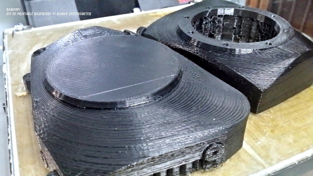
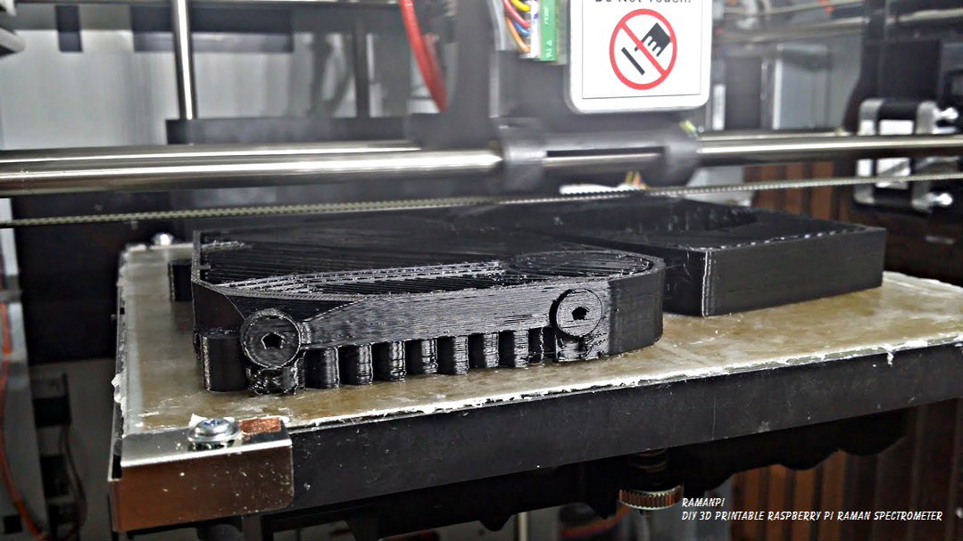
Once you've removed it from the printer... There's going to be a little cleanup required... All the supports, and rough edges, screwholes and everything need to be free of debris, etc..
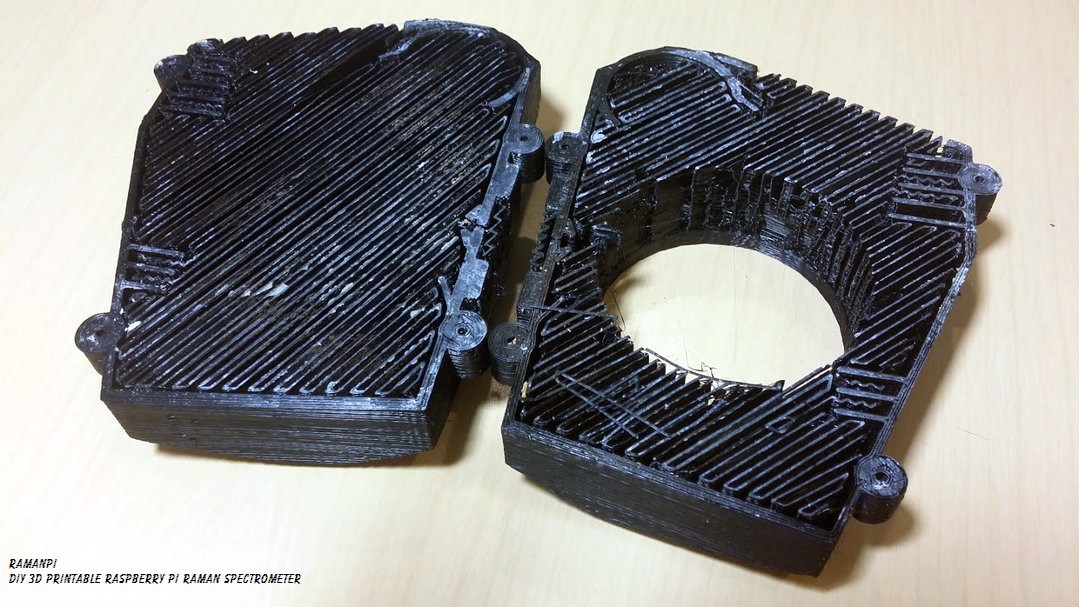
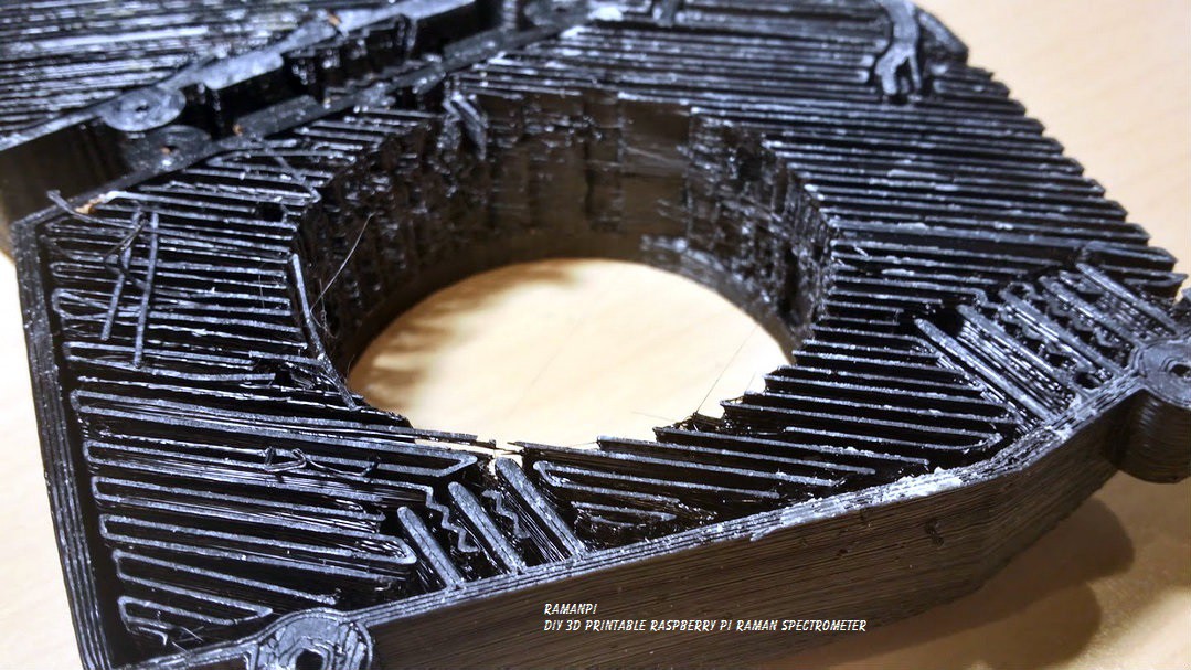
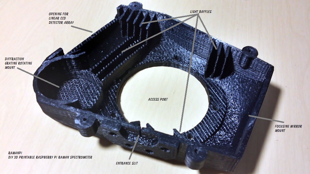
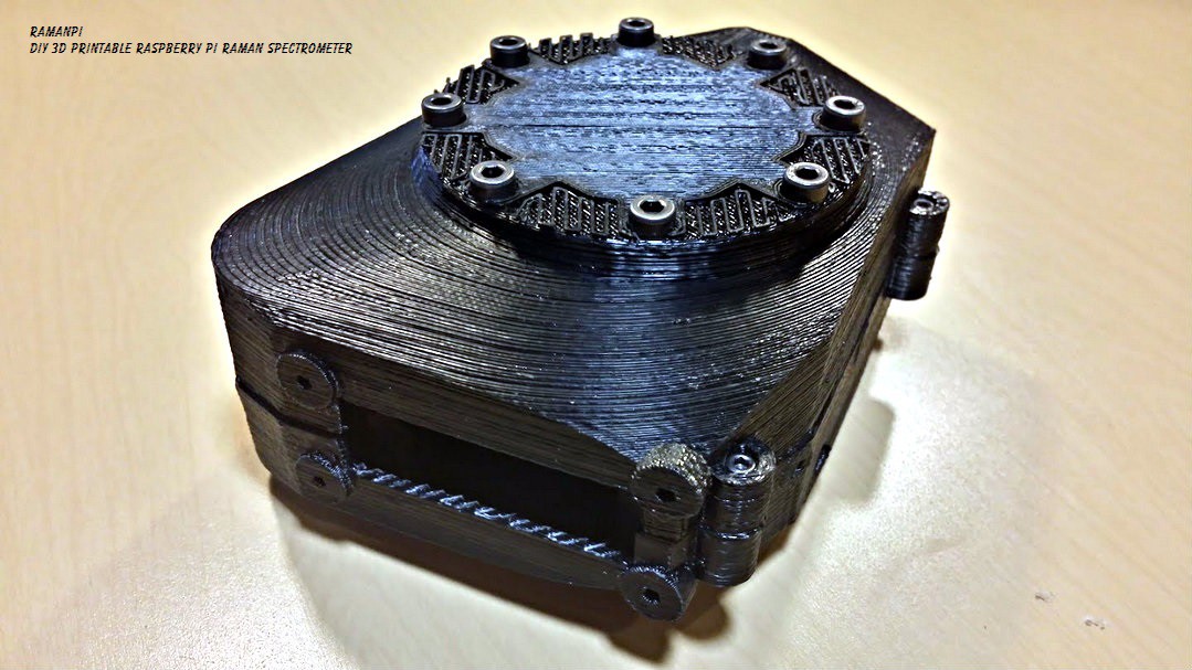
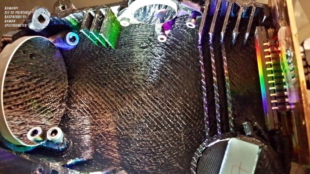
Once you get that all cleaned up.. Your spectrometer parts should look something like this...
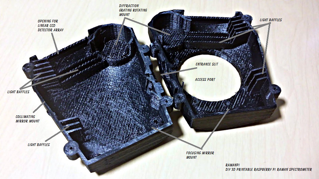
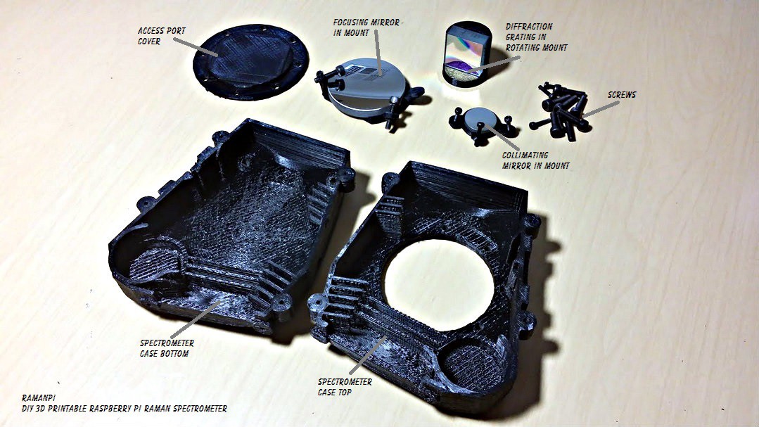
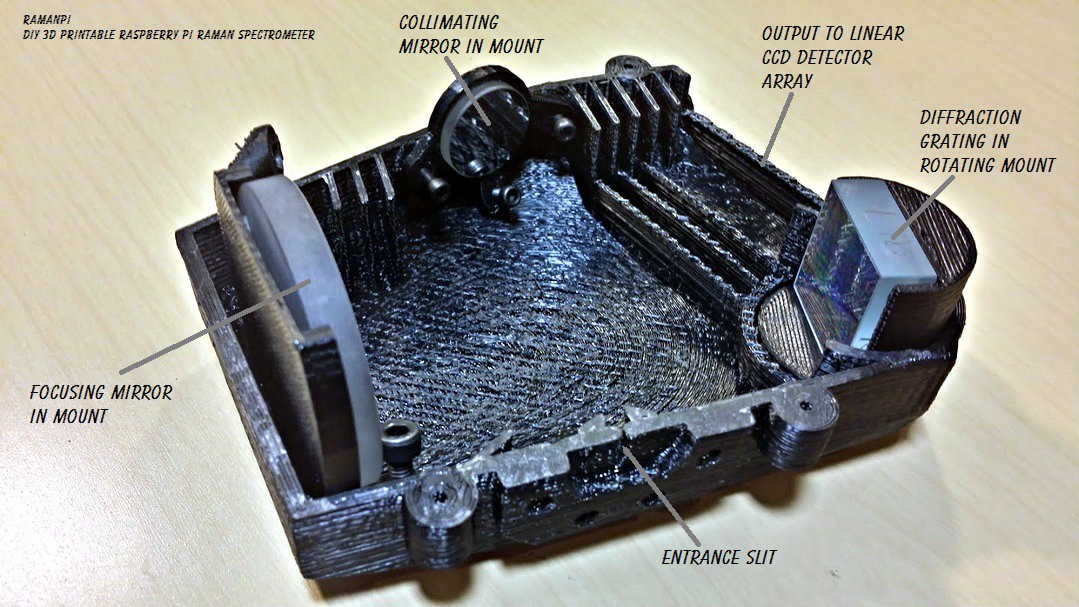
Gather your other parts... The access port cover, the necessary screws, the diffraction grating..the collimating mirror, the focusing mirror...the mounts for the optics...your imaging board and the CCD board...
Here are the parts I designed this version of the spectrometer to use..and is what I am using in mine..
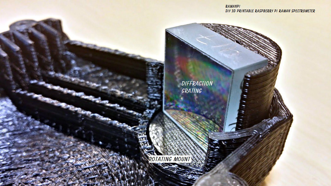
The diffraction grating... Stock No. #43-216
- Edmund Optics 1200 Grooves/mm, 25mm Square, VIS Holographic Grating ...... $135.00
The collimating mirror.... Stock No. #46-239
- Edmund Optics 20mm Dia x 80mm Focal Length, Spherical Mirror ....................... $37.50
The focusing mirror... Stock No. #43-471
- Edmund Optics 50mm Dia. x 100mm FL Protected Aluminum, Concave Mirror ... $42.50
I'll post the specifics on mounting the optics in their mounts soon, but for the moment, lets assume they're already mounted..
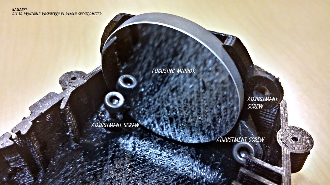
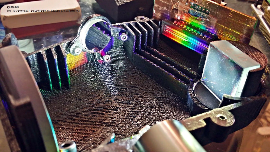
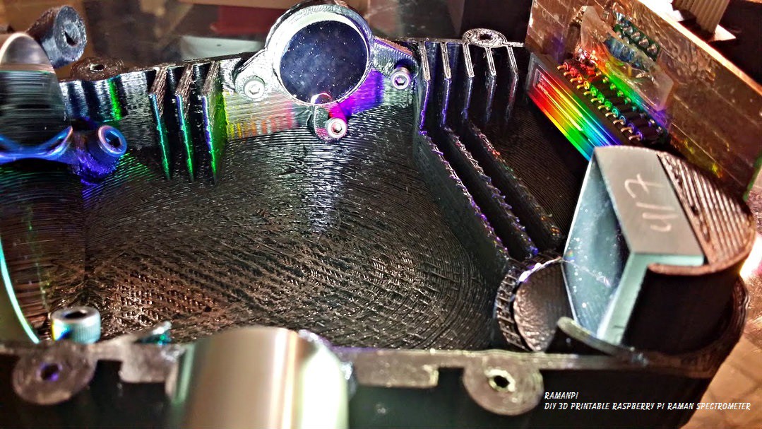
Go ahead an place the focusing mirror assembly in place and screw in the adjusting screws...
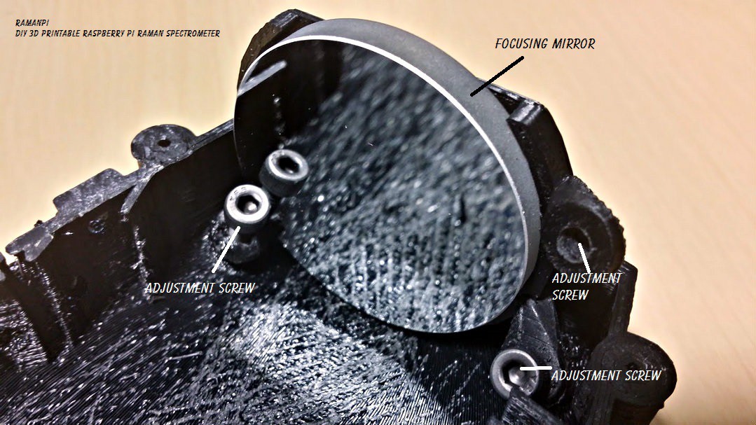
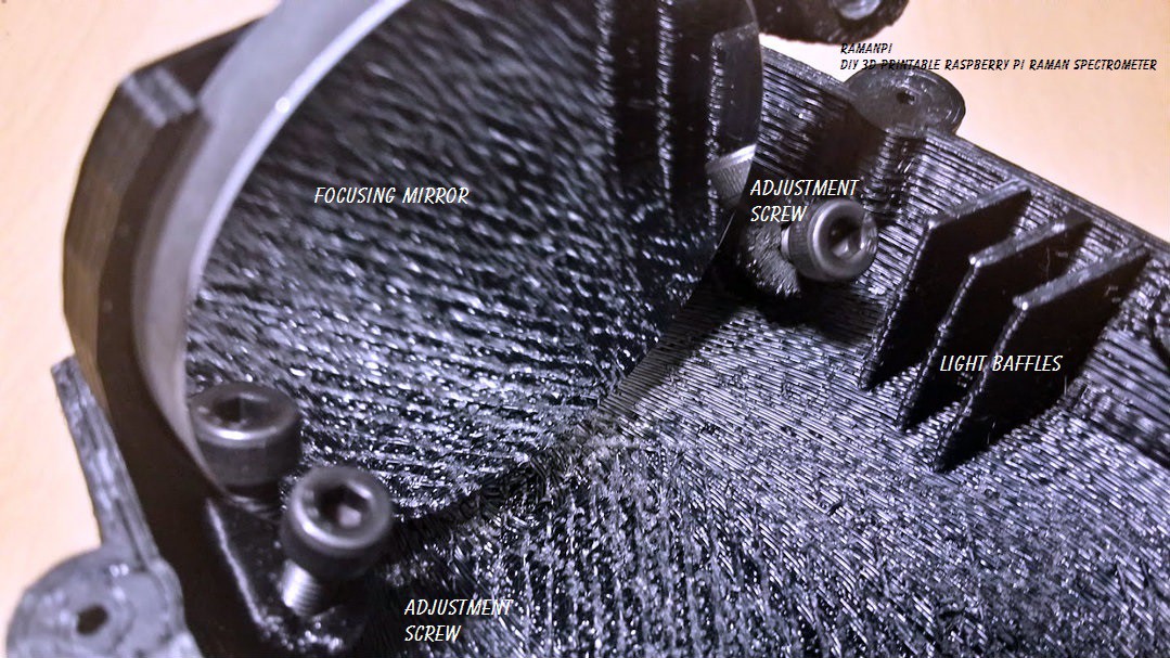
And always... make sure you're wearing proper gloves, and not to touch the surface of the optics!!!
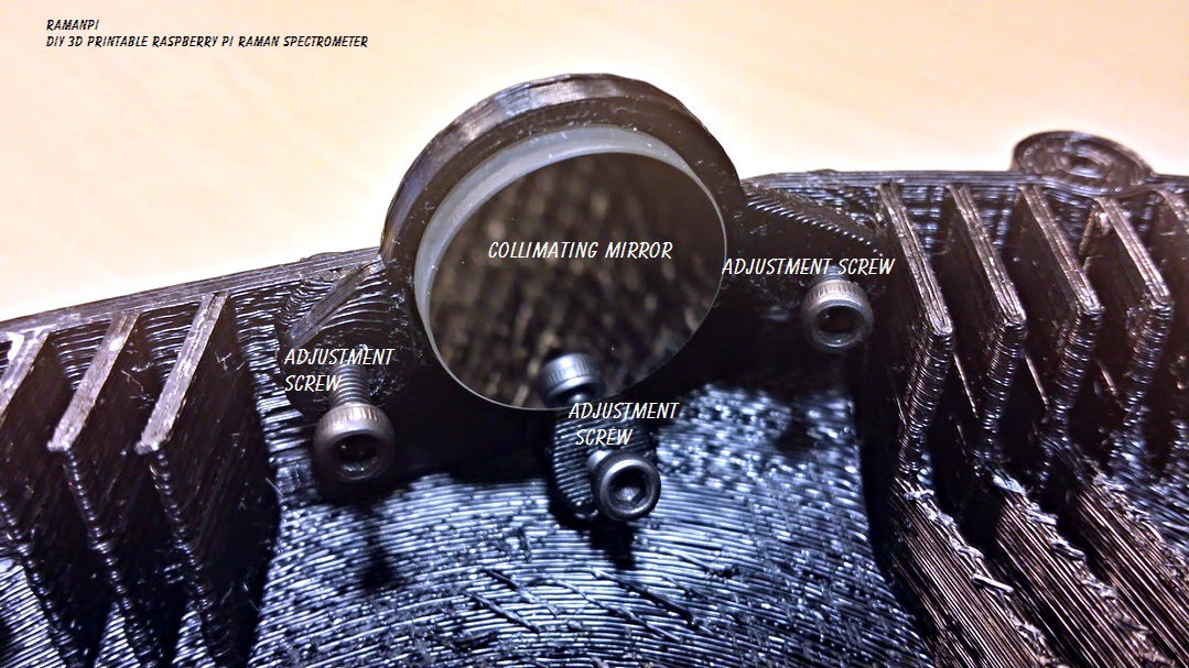
Now, let's go ahead and place the collimating mirror assembly into place and screw it in...
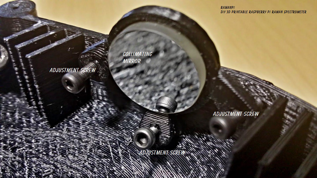
Again, make sure to be very careful not to touch the surface!
Once that's in place, go ahead and place the diffraction grating assembly in...
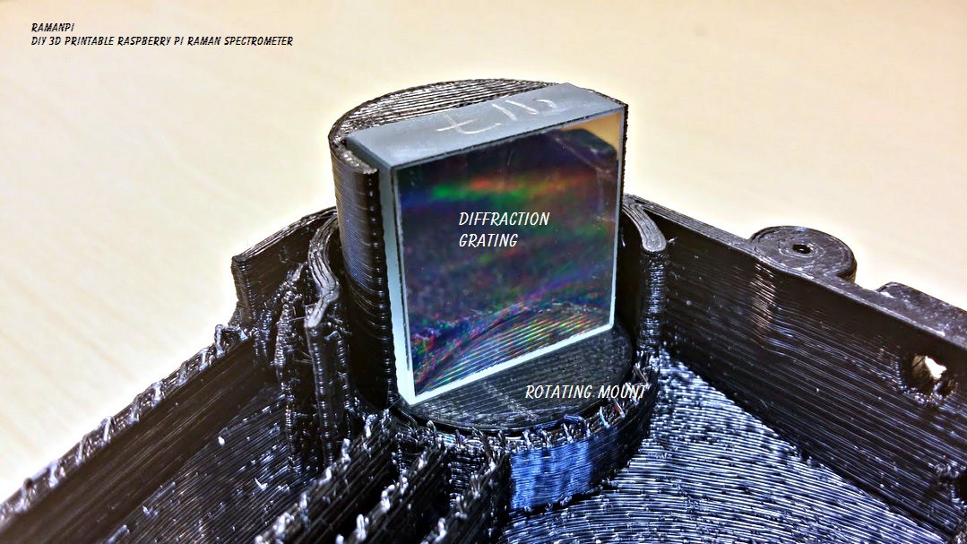
BE EXTRA SUPER VERY MAJORLY CRAZY ULTRA CAREFUL NOT TO TOUCH THE DIFFRACTION GRATING SURFACE!!!!!!!!!!!!!!! ANY CONTACT WILL RUIN IT... Just look at mine... :( It fell on it's face on a very clean surface and is going to have to be replaced...
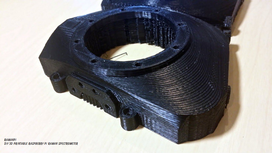
Here is what you should have at this point... A very nice start!
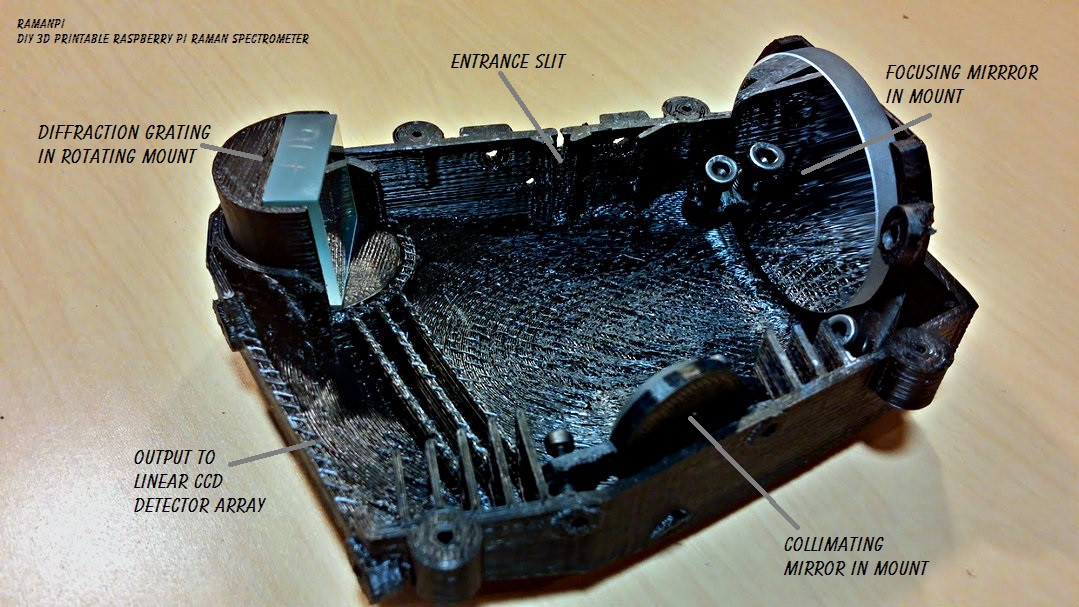
At this point, your optics are probably going to be way out of alignment.. We'll have to make sure they're all snug and aligned before we can use this thing for anything...
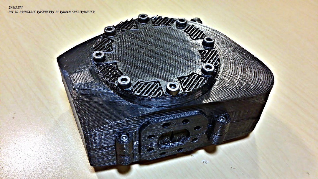
But we'll cover alignment in another project log as well... For now, let's follow through with getting this thing assembled! Take your top and the access port cover...get the mounting screws........
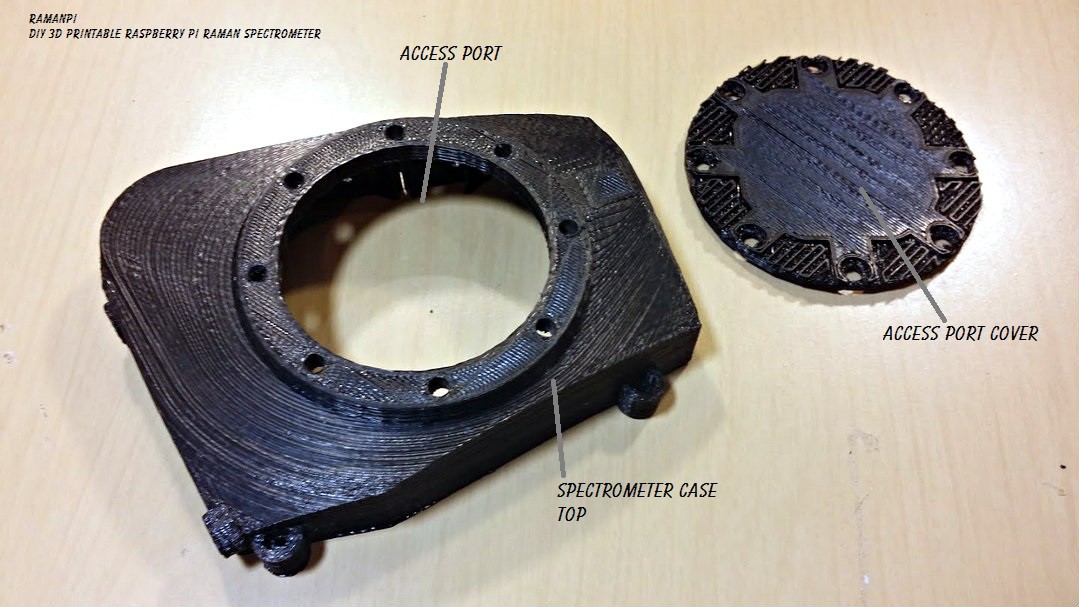
Place the access cover over the access port and align the holes....
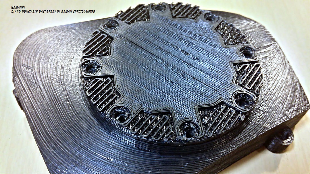
Place the screws in place and start tightening them! I recommend an alternating pattern...
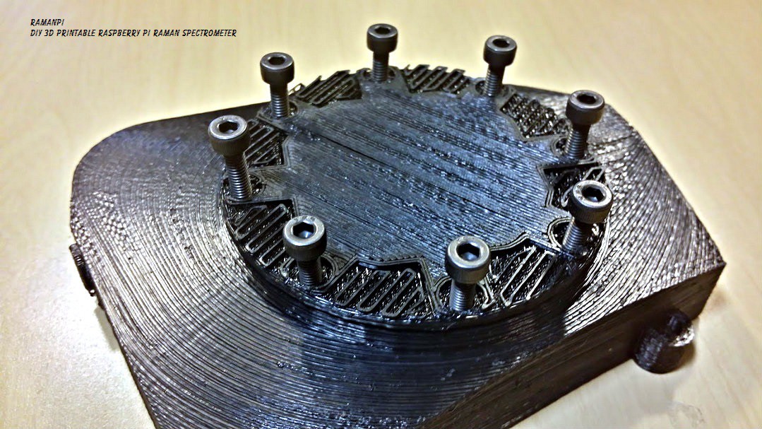
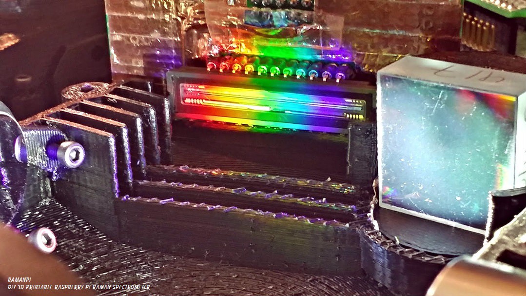
And there we have a spectrometer!! Almost ready for use!
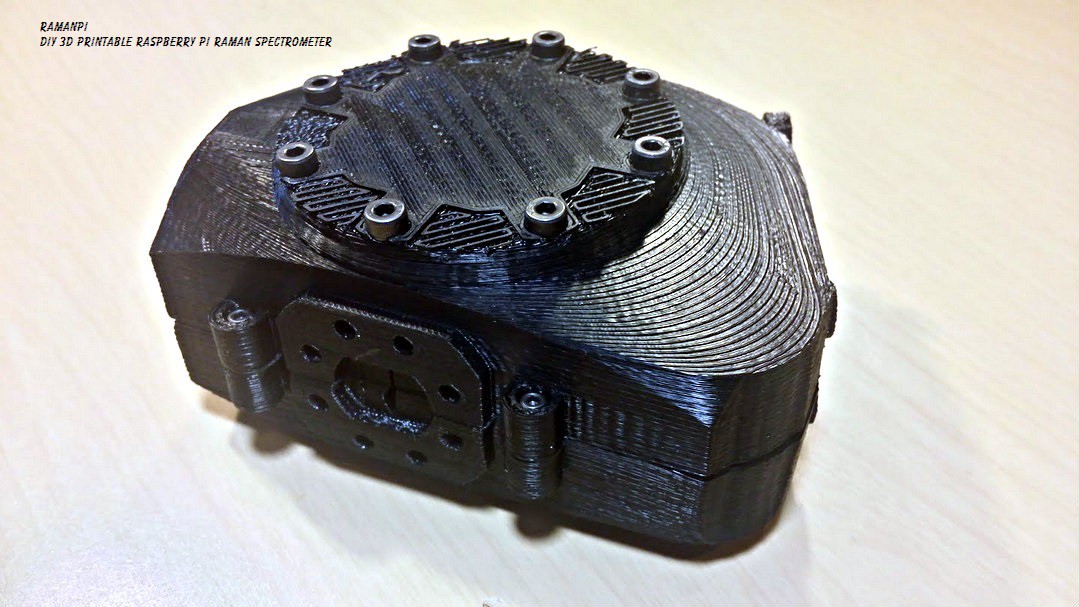
We will cover placing the CCD board in another post as well... But this is where it goes.. :)
Looks great doesn't it???
Here's some sneak preview pictures of the alignment process...
If you can't tell, I'm pretty happy with how this part came out.....
I'll be picking up where I left off with the electronics and software now... And I am aiming for raman spectra by the end of the month!! This is a quick little test I did (not calibrated) using some filters... More on this soon!!!
Does this look good on me?
LOL...

Edit:
A little better example of the 532nm laser... I think I had the beam misaligned on the first image... This one's not as strong, but I closed the entrance slit a tiny bit...
Update: 09.18.2014
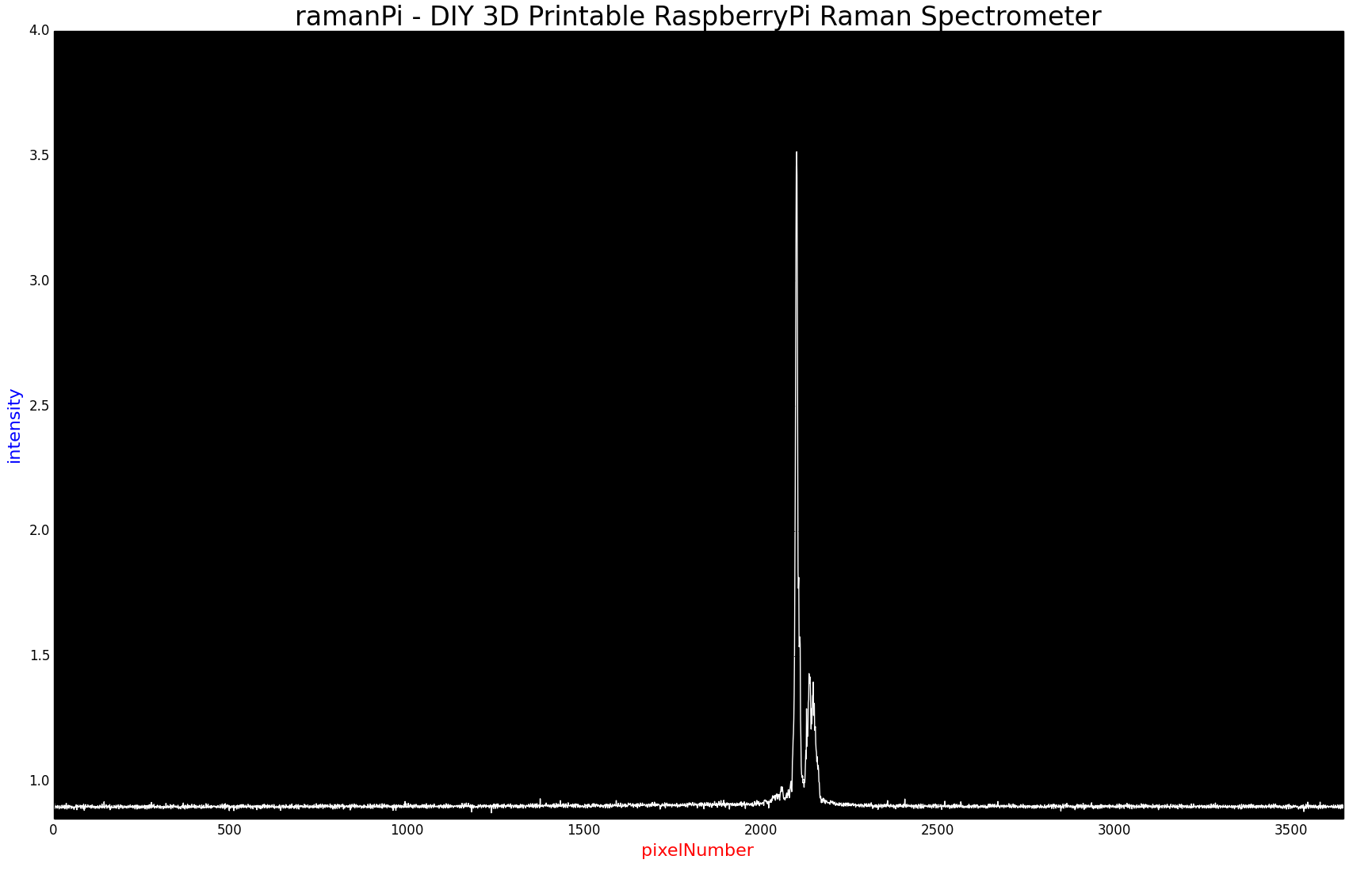
Here is a much better signal from a better aligned laser in the test stand bolted to the side...

Update Log:
09.17.2014 - Started maintaining this post as a living document.. Added Title to start of instructions.
09.18.2014 - Added 532nm laser spectrum update at bottom...
09.23.2014 - New Logo
Discussions
Become a Hackaday.io Member
Create an account to leave a comment. Already have an account? Log In.
http://bwtek.com/spectrometer-part-4-the-optical-bench;
Holographic setup only needs 1 piece of grating.
Hi, I found a piece of concave holographic grating for $90.
http://taomsun.en.alibaba.com/product/60016892882-800327480/A2_Holographic_concave_grating.html
This setup should save you quite a bit of money
Are you sure? yes | no
That link didn't work... But the grating I went with was only $135 from edmund optics.. In order to use a concave grating, you'll need to change the entire geometry of the spectrometer... and the way the scad file works to accommodate that... I started with a concave grating as you might have read in some of the history and had no luck...
Let me know how it works!
Are you sure? yes | no
OK, the link fixed. anyway, 1 concave grating=$90 versus your grating 130+70 (2 mirrors)=$200. OK I try it out. I look for cheapest way to do it.
Are you sure? yes | no
If that holographic grating is not a flat field type then it will work badly with a linear sensor. This has been covered in other comments. It may not be sold anymore, I was only able to find details in google cache.
Are you sure? yes | no
Is there an internet database already existed that contain reference data for different material we can compare our result against in order to help us determine the chemicals of the samples? Or we have to start from scratch?
Are you sure? yes | no
There are several.. I have obtained permission for free access to one, and am working on as many others as I can... Most of the larger ones are fairly expensive. I'd be very happy if one of those companies allowed at least limited access for ramanPi users :)
I also have put some thought into a peer to peer network for ramanPi users to establish and contribute to a public open access database...
Are you sure? yes | no
hi regarding to slit width, you mentioned you purchased a 10um one, is that matched with pixel width of the CCD? according to reference 10um is the minimum, next is 25um, 50um, 100um and so on. It says the slit as wide as possible to increase throughput when optical condition is satisfied.
Are you sure? yes | no
The pixel width of the CCD I am using is something like 8um.. Oversimplified, a wider slit lets more light through, and decreases resolution.... I'd recommend some research before purchasing to decide which width is best for you...they're fairly expensive..
Try emailing me here http://www.meridian-scientific.com/contact.html and I'll answer your questions.. It's getting a little confusing with multiple questions in multiple places.. :)
Are you sure? yes | no
Because you are using CT setup you don't need that expensive holographic grating. Two typed grating, cheaper ruled grating and expensive holographic gratings.
The Concave Holographic bench setup using one piece of concave holographic grating instead of one planar grating and two mirrors of your Czerny-Turner setup.Any reason not using concave holographic setting?
Are you sure? yes | no
Not entirely sure I understand your question... I started off with a holographic grating, there are a number of problems with it. And if I understand correctly, the type of grating you are talking about is very expensive..
Try emailing me here http://www.meridian-scientific.com/contact.html and I'll answer your questions.. It's getting a little confusing with multiple questions in multiple places.. :)
Are you sure? yes | no
Great work! Have you seen those man held portable Raman Spectroscopy tool? Why do you think it can be done so small space? Do you think you can do a portable one? Its no more bigger than a handheld power drill tool?
Are you sure? yes | no
I have. I haven't really looked into it too much yet, but I assume they use spectrometers based on devices like this http://www.hamamatsu.com/us/en/C12666MA.html Not sure what they do for temperature control or compensation, or a lot of other stuff yet....but A small laser diode, the right optics and that spectrometer along with an FPGA probably would do it..
I do have plans on creating a hand held unit.. I see no reason it can't be done... But after I finish this one and get the kits available to everyone.. :)
Are you sure? yes | no
Why need a expensive diffraction grating material. Youtube posters have mentioned to use regular DVD material and cut it out for diffraction.
Are you sure? yes | no
It depends on what you want from the device. Its mostly about spectral resolution. I am in the process of designing 3 versions of this device.. Low Medium and Higher quality/price.. The lower quality version is probably going to end up with a transmission grating, not a slice of DVD...but still a lower priced grating similar to the way the DVD works. This version will also use the raspberryPi camera module and cost much less.. The Medium and High will still use reflection gratings because a lot of people want higher resolution and predictable results... The high will probably be more temperature controlled, and offer metal parts, etc..
Are you sure? yes | no
You might be able to do both in an LGL geometry. Thor has transmission gratings for $75, and regular pcx lenses are pretty cheap...though you may need/want achromats (and certainly if you were really trying to nail that 10um slit width). It would probably cost about half of the crossed czerny design with similar performance. If you wanted to go really cheap, you might be able to get away with a holographic film, but you'd want to make sure it was stretched and epoxied really flat over something like a microscope slide. It may not work very well, but if it did, it would be virtually free.
I've seen a design for an adjustable slit using razor blades and a micrometer knob. I bet I could come up with something for <$30.
Are you sure? yes | no
Aside from needing acromats another problem with a lens design is that every extra surface is also a reflector.
Are you sure? yes | no
I really want to know how to design the position of the optical elements in your spectrometer.Looking forward to your reply, thank you
Are you sure? yes | no
Hi.. You might take a look at the github and look at the files for the spectrometer... I am still in the process of refining it, but the spectrometer file basically designs itself.. You can alter the optics parameters and it will reshape and redesign the spectrometer based on your parts... Hope that helps..
Are you sure? yes | no
Are you sure? yes | no
If you are interested in the spectrometer portion alone you will need the following files...
Top cover: https://github.com/flatCat1597/ramanSpectrometer/blob/master/hardware/3dPrintable/files_stl/optics_module_spectrometer_v04_topCover.stl
Diffraction Grating Mount: https://github.com/flatCat1597/ramanSpectrometer/blob/master/hardware/3dPrintable/files_stl/optics_module_spectrometer_v04_DGMount.stl
Collimating Mirror Mount: https://github.com/flatCat1597/ramanSpectrometer/blob/master/hardware/3dPrintable/files_stl/optics_module_spectrometer_v04_collimatingMirrorMount.stl
Focusing Mirror Mount: https://github.com/flatCat1597/ramanSpectrometer/blob/master/hardware/3dPrintable/files_stl/optics_module_spectrometer_v04_focusingMirrorMount.stl
Spectrometer Top: https://github.com/flatCat1597/ramanSpectrometer/blob/master/hardware/3dPrintable/files_stl/optics_module_spectrometer_v04_top.stl
Spectrometer Bottom: https://github.com/flatCat1597/ramanSpectrometer/blob/master/hardware/3dPrintable/files_stl/optics_module_spectrometer_v04_bottom.stl
I recommend printing in ABS since the dimensions are adjusted for the shrinkage..
Are you sure? yes | no
Are you sure? yes | no
What type of compensation are you referring to? I don't plan on incorporating any coatings on the sensors optical surface, or cylindrical lenses, etc... Most everything else I imagine will be handled through software...
Are you sure? yes | no
Also, how will you calibrate the sensor, to know which pixel represents a given wavelength? The laser on the last picture seems too wide to say 530something nm is at 2400something pixel...
Are you sure? yes | no
This document has some very valuable information as well... It actually should answer most to all of these questions... http://oceanoptics.com//wp-content/uploads/USB4000-OEM-Data-Sheet.pdf (This spectrometer datasheet actually covers their usage of this exact sensor )
This document covers sensitivity using the TCD1304 in their USB4000 and HR4000 spectrometers... http://oceanoptics.com/wp-content/uploads/HR4000USB4000ShutterPerformanceinHWtrigger3.pdf
Calibration is done with a known light source.. Something like a mercury vapor lamp, or neon, etc... where the spectrum is well established.. you match that and so on... Here's a product made just for this http://oceanoptics.com/product/hg-1/ ....... It's also covered well here http://www.americanlaboratory.com/914-Application-Notes/1596-A-High-Precision-Calibration-Method-for-Spectrometers/ and if you like reading this stuff... here's another http://nvlpubs.nist.gov/nistpubs/jres/114/4/V114.N04.A02.pdf I think you're question also hits on spectral resolution...which is a big topic in itself..things like the entrance slit, diffraction grating etc.. have a large impact on that as well.. http://www.lightforminc.com/Spectral_Resolution/ or https://docs.google.com/presentation/d/1b7WFiBkPIzv3gN22CPkcTePRfbyhFV_yyaNz0sg4agY/edit#slide=id.p51 as well as the other info I provided demonstrates that too.. :)
Edit: Forgot to answer the last question..........
The laser is wide for several reasons.. Gary Firestone's comment below shows one good reason... also, the laser itself isn't perfect.. It's not going to emit at a specific 532nm wavelength, and not have some spillover, harmonics, etc.... Temperature, and a lot of other variables contribute to the width it emits... The 532nm Pass filter helps with this, only allowing 532nm light to pass through it (I wasn't using this filter for the above images), but that doesn't account for the issues Gary mentions...so there's going to be some..but software should be able to account for a lot of it, and that (and a number of other reasons) is why calibration is important... The documentation I provided above explains this pretty well too....particularly the datasheet on the USB4000...
Hope this helps!
Are you sure? yes | no
Are you sure? yes | no
Are you sure? yes | no
Are you sure? yes | no
Are you sure? yes | no
Are you sure? yes | no
I just ordered a 10 micron slit, hopefully it'll be here soon...
Are you sure? yes | no
Are you sure? yes | no
I'll take a shot next to a ruler.. I don't know if a banana would be good.. lol
Are you sure? yes | no
It'll add ~$100 to the BOM, but at least then you'd have a known slit width, and be able to figure out what the spectral resolution should be with perfect alignment, so you'll know when to stop :)
Are you sure? yes | no
Are you sure? yes | no
Are you sure? yes | no
Actually, some amazing spectrometers like the Zeiss MMS1 use fiber optic bundles. You can do the same thing at home. Here's what I did. 1) Buy a bunch of fibers. 2) Lay them out on the table flat. 3) Place tape over them to keep them together. 4) Cut one end. Wala! you have a perfect slit. Now you can bundle the other end of fibers and couple them to a typical fiber optic connector (like most spectrometers).
Are you sure? yes | no
Are you sure? yes | no
Are you sure? yes | no
Are you sure? yes | no
Any idea why the spectrum of the laser pointer looks strange -- the right hand side just kind of drops instead of having a gaussian shape? Once it looks normal you can measure the FWHM/spectral resolution, and see how well you can tune it! (It looks like, continuing the curve you can kind of estimate that the FWHM might be around about 50 pixels, which would be about 5nm, if I'm estimating things correctly?)
Are you sure? yes | no
The spectrum might look strange because I think I had an alignment issue.. I just posted an updated image that's a little (not much) better.. Through this bit, I've learned there are two things I need to do in the next day or two.. 1. Make a solid mount that mates to the side of the spectrometer for testing and calibration, and the 2nd is hang a connector on the imagingBoard that will control the laser pointer so I don't have to push the button and move it around while it's taking a sample... What I have now is a nightmare for alignment and consistency.. I'll be doing a series of posts.. This one was putting the parts together, another will be alignment, another for mounting the optics, another for calibration, etc... I'll try to get a better spectrum of the laser tonight.. Maybe I can get the software to count the width... that might be useful in itself..
Are you sure? yes | no