 fl@C@
fl@C@

Note: This log entry is a living document. I'll be updating this post to reflect the current configuration as time goes on.. There will also be a log at the end of the post noting modifications to the log, etc..
UPDATED-----> 09.23.2014

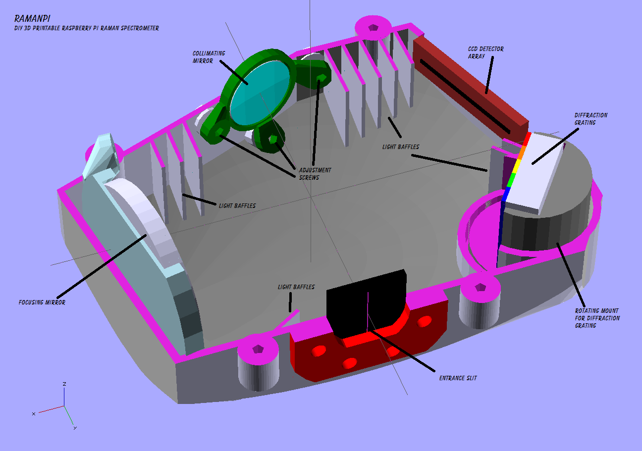
Once you've assembled your spectrometer, you'll need to align the optics so the light coming in through the entrance slit makes it to it's destination....the detector array... The light will enter through the entrance slit, hit the collimating mirror where it is directed in an orderly path to the diffraction grating...at this point, the light will be split into the colors it's composed of....that light is reflected off the grating onto the focusing or 'imaging' mirror...from there it is focused onto the detector array where it's read out to the microcontroller and passed to the raspberryPi for processing...and so on..
To align your spectrometer, you will have had to assemble it following the instructions in this post.. Which means you'll have all the parts necessary and are ready to go..
Alignment is pretty straight forward..There are some precautions to take, and you'll need a couple tools.. You need a 2mm and 4mm allen wrench or driver...I recommend the driver as the bent wrench poses a hazard to scratching your optics if you're not extremely careful..
To do this alignment procedure, I recommend you have a laser pointer and have printed this test stand I designed specifically for this purpose... You'll also need this part x2 which is the top bridge for the mount..

So, let's get started..
FIRST AND FOREMOST---SAFETY!!! WEAR LASER PROTECTION WHILE ALIGNING ANYTHING WITH LASERS!!! 5MW is still enough to cause damage.. Just let it be known I told you so...!!
For now, it's easiest if we start with the top half of the spectrometer removed.. This will make life easier when trying to access the adjustment screws, etc.. The access port gives a good perspective, and allows for minor maintenance but I'd recommend against starting your alignment through the port..
You should be looking at something like this...

First, lets start by attaching the test stand... You can attach the test stand to the side of the spectrometer at the entrance slit flange using a few M4 hex screws..The same type as the access cover lid on the spectrometer. The test stand also has a receptacle for a vial which you can use later for other fun stuff.. :)
After attaching, you should be seeing something like this...

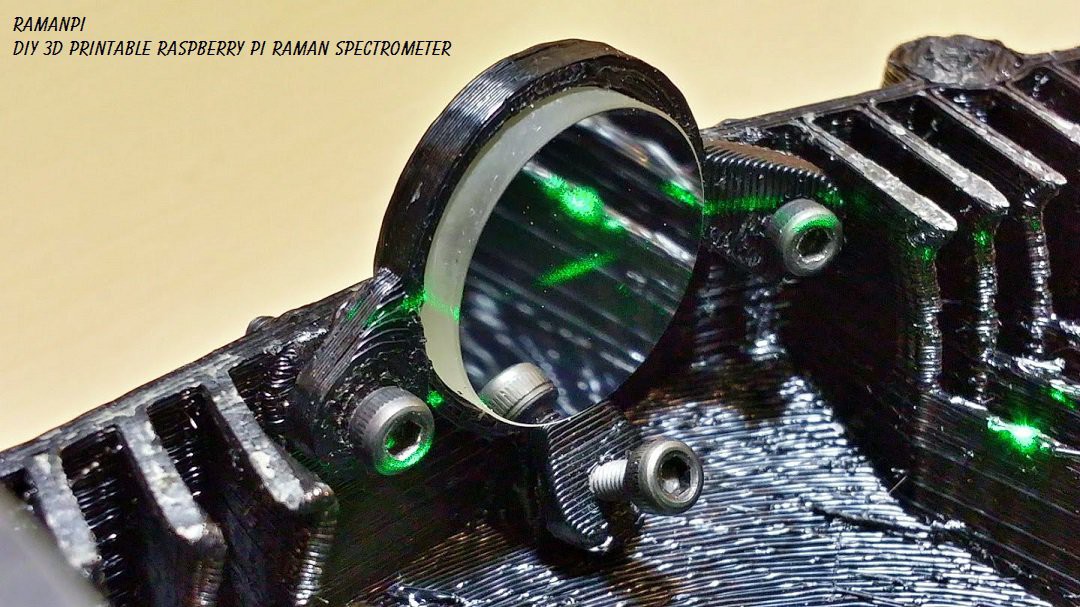
Once that is in place, turn the laser on and see where the light is ending up...It really should be hitting square in the center of the collimating mirror...If not, you have some issues..Start by making sure your laser is in the stand properly..and making sure the stand is mounted on the side of the spectrometer correctly..
With the laser on, you should see something similar to this on the collimating mirror...
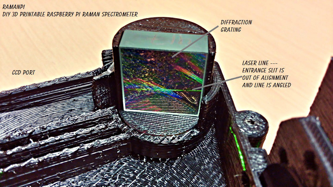
Next, with the laser on, take a look at the diffraction grating...You should be seeing a horizontal line across it...probably not centered... You'll have to adjust the three screws on the collimating mirror mount to align this.. The left screw clockwise pulls the line to the right on the grating... the right screw clockwise pulls the line to the left.. The bottom screw clockwise pulls the line downward on the grating... Both left and right screws clockwise will pull the line up... A combination of the three will allow for centering.. It takes a gentle touch and some patience..
When you are done, you should see something like this.... (Notice in this image, the entrance slit is slightly angled causing the line across the diffraction grating to be angled.)
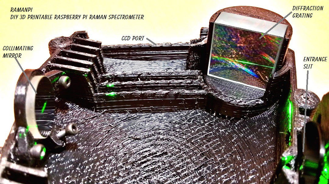
After that, you'll want to make sure the grating is reflecting the correct order onto the focusing mirror.. This will take even more patience.. And keep in mind, this is something trained professional normally do with commercial products..they usually cement the optics in place after someone has aligned them so you can't make a mistake.. To align the grating, it really only goes left or right in the rotating mount.. So, depending on your optics and grating...if it varies from my initial configuration, you'll need to do some math.. Or hopefully I'll have completed the .scad to correctly give the proper angle for the grating.. At the time of this update, it's not working 100%.. But this works until then.. Hit the power on your laser, and put the palm of your hand where the CCD goes...or if you already have your CCD mounted, look where the beam is hitting... You should also be able to see where the beam is hitting the focusing mirror... You should see the reflection of the beam off to the side of the mirror..You do not want the actual reflection pointed at the mirror...If you hold the palm of your hand to the left behind the focusing mirror you should see the beam.. Basically you want the beam to hit the focusing mirror about half way.. This image should be of some use.... Notice where the grating normal is pointed.. Then take note where the focusing mirror normal is pointed.. Orient the grating so the 1st order is just to the right from the front of the mirror) of center.. You should see the beam somewhere on your CCD board...(or palm of your hand held near the CCD port.
It should look like this.....

Next, the focusing mirror needs to be aligned.. Use the adjustment screws in the same fashion as the collimating mirror to direct the beam to the center of the CCD... Should be pretty straight forward...
It should look like this....
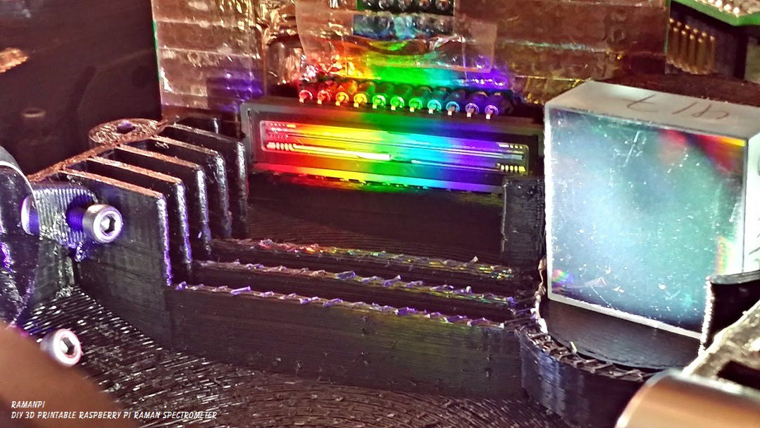
If you've followed these steps (and all the previous steps leading to this) properly.. You should be ready for some fun... Just as a quick test... Try replacing the laser pointer with a pocket flashlight... The spectra should start with red at the left of the CCD and Violet to the right... And be centered on the CCD...
It should look like this.....
From here, you will need a known light source to calibrate any further... That will be covered in the next log entry on Spectrometer Calibration...
Until then, enjoy!

UPDATE LOG:
09.17.2014 - New Entry for Spectrometer Alignment
09.18.2014 - Corrected date format
09.22.2014 - Added Spectrometer Alignment Graphic
09.23.2014 - New Logo
Discussions
Become a Hackaday.io Member
Create an account to leave a comment. Already have an account? Log In.
Are you sure? yes | no
I am using rubber grommets at the moment because I haven't been able to find small springs anywhere.. Do you know a source? I found these, but I don't think they're exactly looking for.. http://www.standa.lt/products/catalog/fine_adjustment?item=32 ... I haven't had time in all the rush with the contest to do a better search... I'm looking at McMaster Carr when I get a chance...
Are you sure? yes | no
Thanks!
Are you sure? yes | no