Close

Raman

A project log for ramanPi - Raman Spectrometer

The open source 3D Printable Raman Spectrometer using a RaspberryPi and easy to find off the shelf components..

flcfl@C@ 10/23/2014 at 18:024 Comments

Here it is... 1st raman... Not much to look at, and it's on the scope.. But, none the less it is a milestone.

I've spent the past week making leaps in getting the sensitivity required to read this signal.. The return is incredibly weak.. As you can see, there's still some distance to go.

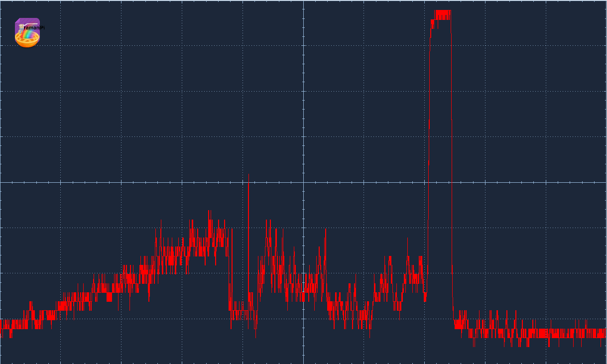
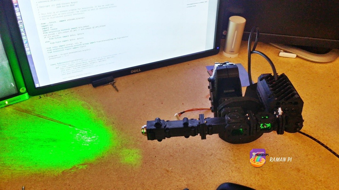
To obtain this spectra (of my hand near the objective), and save my sanity... I have the optics sitting on my bench outside the case where I can get my test probes and everything connected without frustration..

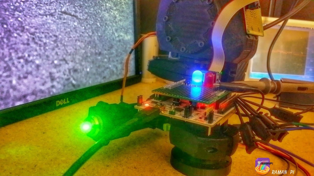
I had to completely re-write the code for the imagingBoard to do this as well.. Having never touched a CCD outside whatever cameras and phones I've owned... Driving one from a microcontroller is apparently an art...one that took some time to even understand how the timing really works sine the toshiba documentation is not terribly informative.. I'll do a nice write up on what I've learned about driving these things soon.. For now, let's just say that easy isn't how I'd describe it. I resorted to using the mBed RTOS to get the stm32 to read, capture and send data... I'm still playing around with the advantages/disadvantages to driving the clocks with PWM, vs using busOut and so on.. But for now...This is where it lies..

I'm very happy with where this is going... With my recent success in getting the software off the ground, and posting the spectra on plot.ly....I really think that makes collaborative 'crowd-science' possible.. There, I think I termed a new phrase while I'm at it.. :)

I should also mention, the firmware (which is still in development) is posted to the gitHub... So, if you're interested in where that's headed... You can take a look.!

"No, really... Just look right in there....." Seriously.....here's good reason to wear eye protection while working with this.....this beam is not even half the original power...

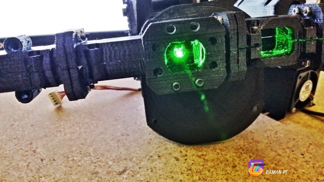
This thing gives new meaning for me to the term Optical Radiation..... ;) Mind you, this is with the splitter in place...

Maybe not contest winning progress....but it is progress and this is a huge project.. I've kind of decided to not rush and just move at the right pace to do things right here... I really want to make this project useful for people, winning a prize is great...but I also want to open doors for education and amateur researchers..

Discussions

peter jansen wrote 10/24/2014 at 01:57 point
I just had a read of the TCD1304AP datasheet, and it looks very similar to the Hamamatsu CCD, so I think you're in luck. The trick with trying to drive embedded devices (like CCDs) that have strict timing requirements is that you generally have to write the timing-critical code in one big function, and be okay with it blocking -- if ISRs are called, they'll often throw off the timing (and so it's okay to disable them, you just have to account for it in the design). So a common way of setting this up would be RaspPi -> Microcontroller (arduino/mbed) -> CCD. The microcontroller would sit waiting on (say) the serial console, waiting for the Raspberry Pi to send it a command, say "sample 1000ms". The microcontroller would then stop listening to the serial port, start it's timing-critical function (sending the clock pulses to the CCD and simultaneously reading the data out), and when done, dump that data back over the serial port (and start listening for subsequent sample requests). Using the PWM for a master clock isn't an ideal choice since you won't be able to sync it up with the rest of the IO pins that you have to toggle. From the datasheet it looks like there are 3 pins you'll need, the Master Pixel Clock (MCLK), which is toggled between 0.8Mhz and 4Mhz, Integration Clear Gate (ICG) which is high when you're not sampling/reading, low when you are, and the Sample/Hold (SH) pulse, which is pulsed once at the start and end of each integration time (the amount you want to sample, probably long for your application). Aside from adding in the ICG pin, this is actually super close to the Hamamatsu code above (even down to having valid data once every 4 clock cycles, like your Panasonic CCD), and the Open Mini Spec code even has the serial console code written in, and a quick processing sketch to get you started on incorporating it into your Python GUI ( http://www.thingiverse.com/thing:148270/#files ). The hitch is that with the TCD1304AP having such fast timing requirements (0.8Mhz min, pg 5), even with the mBed's 12-bit 1MSPS ADC you won't be able to get many samples -- it looks like a maximum of 1 with simple code, and possibly up to 4 samples (pg 6 seems to suggest the output data might be valid for as long as 4 cycles, which would be enough to give you 13-bit). If your Raman signal (The Y axis on your scope image) is more then a dozen millivolts high, that should at least be enough to see it and get your entire prototype workflow complete and outputting Raman spectra before going back to boost the SNR electrically or optically :)

  Are you sure? yes | no

fl@C@ wrote 10/24/2014 at 03:43 point
Hey Peter... I'm not actually using an mBed...just the online compiler and framework.. I'm using the STM32F401RET6 ( http://www.st.com/web/en/catalog/mmc/FM141/SC1169/SS1577/LN1810/PF258797 and http://www.st.com/web/en/catalog/mmc/FM141/SC1169/SS1577/LN1810/PF258797# ) which has a 2.4MSPS 12bit ADC.. I actually have gotten the clocks working well, and have read from the CCD fine..many posts show those results... my problem has been streaming the serial data while sampling... It's only been the past week or so that I've tried several different methods of driving the clocks in attempts to multitask and send the data out the serial port at the same time it's reading the next sample.. Originally I was driving the master clock and shift gate (SH) with PWM and toggling the ICG when appropriate during the cycle... Works great....and has produced a lot of what I've posted.. My problem rose when trying to increase the integration time with that method...as well as sending the data from the previous sample while reading the next... I believe sample hold is controlled by a condition where you keep the shift gate and icg lines in a state (I can't remember off the top of my head which is high and which is low) until you start the clocks again.. I'm not entirely sure how else I'd set up the architecture...the raspberryPi sits in the middle for all the microcontrollers and issues commands to whichever is needed based on whatever task is requested... So, if the user wants to open the cuvette tray and issues the command from the workstation...the raspi sends that command to the controlBoard...if they issue the command from the touch panel, the interfaceBoard sends the request to the raspi who then delegates the command to the controlBoard...When a user requests spectra...the raspi orchestrates whatever is needed among all the microcontrollers to perform the necessary tasks....from switching on the laser to moving the filter wheel and displaying the progress on the front face LCD..
In my experience with blocking code and ISRs, it does more than throw off the timing..it locks the mcu.. Which is why I was experimenting with RTOS.. You can make blocking calls in a thread without nailing the processor... The problem with my approach in the examples I think is more how I handled sampling the ADC and driving the clocks.. In my original attempt, I synchronized the PWM signals using an interrupt...the tolerances were close enough that it works.. I have a lot of things to try still.. I like using the busout instead of PWM, so I might try using 'signal flags' to indicate to the other thread when to act.. Seems that should be faster than an interrupt.. Maybe a good way to synchronize...set up three threads, SH-ICG-MASTER and use signals between them to indicate the state.. I doubt that'd be fast enough though... one thing I do know.......getting 0.8mHZ or 1mHz from busout or bitbanging the ports doesn't get you there...not without addressing the registers directly....PWM through the mBed libraries won't even get you that much...the fastest PWM you can generate using them is 500kHz.. The FastPWM library seems to do 2.4mHZ on the 401RE chip which is more than enough though,...unfortunately that is where my troubles began...I think it's a bit of a cpu hog..
The thought has occurred to me that it might be worth a look at scrapping the mBed libraries and take a look at ST Micro's environment... or the remote possibility of moving to an FPGA for the imagingBoard...or maybe just upgrading to the 100mHz 411 instead of the 84mHZ 401 since most of my recent troubles have been memory (RTOS and storing all 3648 element 16bit sample) and speed (maintaining the duty cycle while pushing data out the serial port)..
Ultimately, that's part of the fun and learning....which is what this is all about..! I will just be happy next week to get more than 3 hours of sleep per day again after how ever many months now.. I'm not afraid to say, there were a few weeks when I didn't sleep for 3 or more days trying to meet these deadlines to get even this far... =)

  Are you sure? yes | no

peter jansen wrote 10/23/2014 at 19:41 point
Congratulations on your first spectra! Is this the (ambient baseline - laser excited) delta? If it is, it looks like (eyeballing the quantization error) that the maximum signal height is about 35 bits on the scope. If you slow down the read speed on your own board, you might still be able to see this by oversampling and averaging, as a means of getting extra resolution. In ideal circumstances, if you average 4 10-bit ADC measurements, it's 2 times more accurate (or equivalent to an 11-bit measurement). 16 10-bit measurements is 4 times more accurate (or equivalent to one 12-bit measurement), and so forth ( sqrt(n) ). If the CCD is sample-and-hold, you can often clock the data out of them fairly slowly -- slow enough to oversample. My Hamamatsu and Open Mini Spectrometer drivers have clocking/ADC read examples (e.g. https://github.com/tricorderproject/arducordermini/blob/master/firmware/test2k/SensorSpecHamamatsu.cpp , line 281 ), just be sure to use an int32 or long if you're adding more than a few measurements together so things don't overflow. Also if you do this, some sensors require a fairly balanced 50/50 duty cycle on the clock line , which you can do in a pinch by doing dummy ADC reads on the inactive clocks. (The code above balances the duty cycle on line 283 with delays, but if you're fighting the SNR and taking long reads, and don't want to measure the ADC time on a scope, you can just read it twice). Feel free to email me directly if you give this a try and run into any bumps and need a quick response!

  Are you sure? yes | no

fl@C@ wrote 10/23/2014 at 21:43 point
Hey Peter.. Thanks.. I've tried seven different ways so far with this.. I ended up with using the RTOS because using blocking code in an ISR doesn't end well... So far, I've had it one way or the other..but not both.. My original code sampled the CCD, stopped the other functions and output the data..then moved on again.... That's not really great if you want a continuous stream (mostly for using the spectrometer outside the raman system).. Problem with all the other methods I've tried so far is that everything works until you do something else.... like the FastPWM library worked great for driving the master clock at 1mHz, but the second you try to read the analog input it freezes everything... So that's why I tried using the BusOut...first without RTOS then with.. without it, I could drive the clocks, but couldn't do much else.. with it and setting the clocks priority to realtime, i could get it to spit data out while driving the clocks simultaneously..which is great.. but the second you try to read from the analog port... dead. I have some hurdles to master with the mBed platform, and I think it is still possibly suffering some bugs on the Nucleo boards... It'd be great if I could get FastPWM or something similar (just manipulate the registers manually) to get the faster clock and be able to read the ccd and push the data all at once...I'm wondering if the Nucleo with mBed is the right choice really.... I still have some ideas, and some testing to try... But I posted this mostly to show that I'm making progress since I haven't posted much lately...and i am happy the optics are doing their job.. :)
You can see a little of what I've got going right now here http://developer.mbed.org/users/flatcat/code/ramanSpectrometer_imagingBoard_v05/file/75c8a8b6b872/main.cpp
And the first FastPWM attempt here... http://developer.mbed.org/users/flatcat/code/imagingBoard_masterClockDrivenTest3/file/ba5ba1fe2798/main.cpp
I'm not familiar with the Hamamatsu sensor, but the datasheet looks a lot more informative than the toshiba chip.. ( http://www.spectronicdevices.com/pdf/TCD1304AP.pdf -- page 6) has three clock signals that have to be coordinated...and what the datasheet doesn't say it that the pixels are output every 4th cycle of the master after the rise of ICG and fall of SH... and the specific timing between ICG falling and SH rising have a tolerance.. I need to get a better understanding of why an ADC read sometimes causes the cpu to lock before I can approach a lot of the smaller details though.. I think what I need most is some time away from the screen to let my brain recover..

  Are you sure? yes | no