 fl@C@
fl@C@
I've been working on getting things tied up with the CCD... I wrote some more sophisticated code to control the CCD, code that allows me to control the exposure and integration times.. It's amazing how sensitive the Toshiba chip is.. I covered the face of the chip with a 1/8" peice of black plastic, then sat a peice of foam over that...and the CCD could still respond quite well to just the reflected light from me lifting my arm two feet away.. All that with very little noise still..about the same amount as my scope captures in my previous post..
So, sources of noise.... This document does a great job of outlining sources of noise in a CCD.. There's shot noise, Reset Noise, Output Amplifier Noise, White Noise, Clocking Noise, Dark Current Noise, Surface Dark Current Noise, Bulk Dark Current, Photo Response Non-Unifiormity(PRNU).. As a side note, apparently these chips are fairly sensitive to IR and prolonged exposure to IR will cause degradation and will increase the PRNU..
There is a lot of give and take with this stuff. I am mainly going to focus on a couple types of noise for this project at this stage.. And I am going to start with Dark Current Noise..
Dark Current Noise
Dark current arises from thermal energy within the silicon lattice comprising the CCD. Electrons are created over time that are independent of the light falling on the detector. These electrons are captured by the CCD's potential wells and counted as signal. Additionally, this increase in signal also carries a statistical fluctuation known as dark current noise. CCDs can be cooled either with thermoelectric coolers (TECs) or liquid nitrogen to reduce this effect. Ideally, the dark current noise should be reduced to a point where its contribution is negligible over a typical exposure time.
In the transfer region, a dark current occurs under the transfer electrode, and its magnitude is proportional to the signal transit time of the CCD analog shift register area: i.e., it is proportional to the product of the clock pulse cycle and the number of shift register transfer steps. Therefore, the dark signal increases as the operating speed decreases. Furthermore, the dark signal output doubles with approximately each 8°C increase in ambient temperature. As previously described, as the operating speed decreases and the ambient temperature rises, the dark signal increases and the dynamic range of the video signals decreases.
Doubling the dark signal output for every 8degrees Celsius is nothing to ignore... This document has some good information.. And I think cooling is probably a good idea.
I did some quick testing with cooling options for the CCD. So, I tried a few combinations of CPU heatsinks and a 12v peltier device.
The first test I did was with a small CPU heatsink with a small fan... I attached a medium sized 12v 40mm peltier hot side to this heatsink .. The fan and the peltier were connected to the 12v output of a 230w ITX power supply.
The surface of the peltier never reached lower than 52 degrees Fahrenheit. I tried the same heatsink above but on the cold side and a larger heatsink on the hot side.. The heatsink on the cold side, after about 20minutes dropped to about 54 degrees.. Meh..
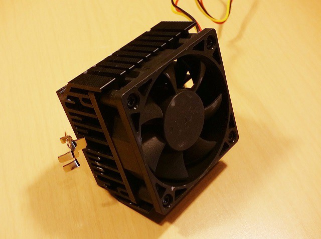
So, I moved to the next option.. A heatsink I removed from an old PC I had laying around.. Same config pretty much as above..Hot side of the peltier to the heatsink and so on..
This heatsink was able to help reduce the surface of the peltier to around 32-36 degrees Fahrenheit.. Pretty big improvement, but still not quite what I was hoping for...
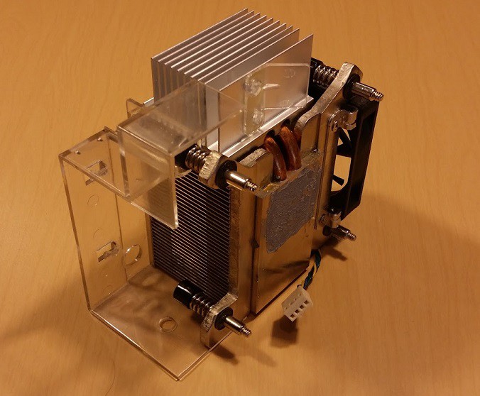
I then, pulled out the crazy...if not impractical try.. This monster.. =D

Ok, so this thing got the surface temperature down to -6 degrees Fahrenheit.. That's -21deg C.. Wow. Same peltier device, same voltage, etc.. Big difference.
I've read that going to -50C isn't uncommon...a lot of systems use liquid nitrogen.. I am waiting on an eBay order for some various peltiers and I will see if I can eek any better results with a smaller heat sink.. I had a thought about stacking or staging them, and apparently there are people doing it.. I still need to look into that, but it doesn't appear to be much more efficient. I will also know better what I can fit into the case after I complete the spectrometer design.. (The optics arrived today so I can get that going!) As far as physical contact with the CCD chip itself to transfer the heat, I am thinking that I will mount the chip on a dual sip socket so it has about 13mm clearance under it and between the pins.. and a 12.5mm square copper bar will fit under and wrap to the underside of the PCB into a sort of coil..like a heatpipe... The peltier will sit on this flat coil.. I am waiting for parts for that..hopefully that idea works..it seemed the simplest thing to reproduce for people since you can buy the copper bar on amazon pretty cheap.
>edit: See comments below.. I need to do my homework on the 'heat pipe'... :)

Discussions
Become a Hackaday.io Member
Create an account to leave a comment. Already have an account? Log In.
Solid copper bar does not act as a heat pipe, I'm not sure where you are going with that.
I like the idea of cooling the CCD, I have plans to try this for some other applications, but if the system is not sealed condensation could play merry hell. It might be best to get the spectrometer working and add this if needed.
Are you sure? yes | no
That is a good point to know! Ha.. I never really looked into the actual physics or anything with heat pipes and made an incorrect assumption! Thank you. There does seem to be quite a bit more to them ( http://en.wikipedia.org/wiki/Heat_pipe ) than solid copper.. :) I still think it might work if you were to use actual heat pipe, I've seen sections for sale on eBay.. It might be worth a look, unless you have more insight..!
I agree, I will most likely wait on the cooling.. But I'd like to keep it in mind while designing everything so I don't design myself in a corner with that..
I had thought of moisture too... Medix and I had a short talk about cooling here - http://hackaday.com/2014/07/31/diy-usb-spectrometer-actually-works/#comments .. It's not just the moisture that concerned me too.. I think being sealed and having a healthy amount of insulation would be good because I think the temperature might be a problem with the 3d printed parts as well...
Are you sure? yes | no