 fl@C@
fl@C@
So.. Here it is... Success.. This is just a test rig, and it's not raman spectra (yet).. but this is my linear ccd setup, with the Crossed Czerny-Turner Configuration..using the optics from Edmund Optics.

This is using the 3D printed parts I threw together a day or so ago... and I have been waiting for them to finish printing for a couple days now..... Well, that wait is over and my first round of tests have some results..
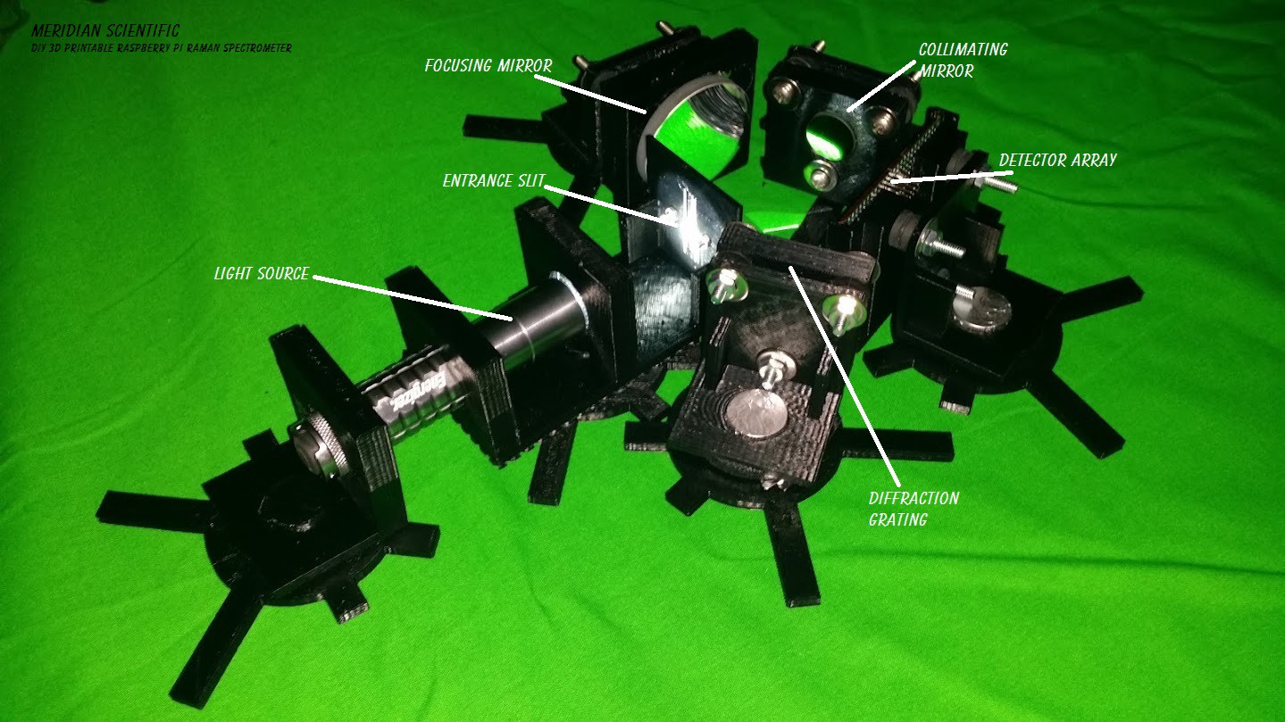
Here is an overhead view of the test setup.. For this simple test, I'm using an LED flashlight.. Nothing fancy to start with.. Mind you these are just throwaway stands I whipped up for this test..they won't go into the final design...
Here's my CCD Board that I'm using for this test.. I haven't added any ADC since I haven't started that part yet, I'm just using a scope for this round.. and I'll be using the 12bit ADC in the Nucleo for the next round.. I'm going to give the mBed 'Fast ADC' library a try for starters... So again, nothing fancy..
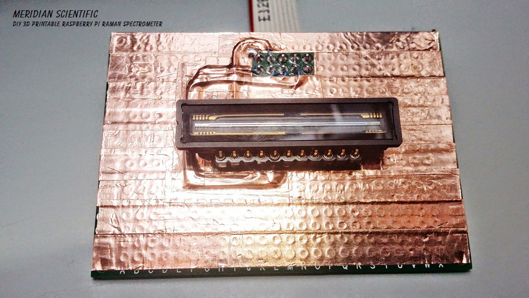
A little closer up... This is the Toshiba TCD1304DG.. Same (except for packaging- this one's ceramic not plastic) that the Ocean Optics, and other major brands use.. I got it on eBay for 15 bucks. They still sell new for around $22..

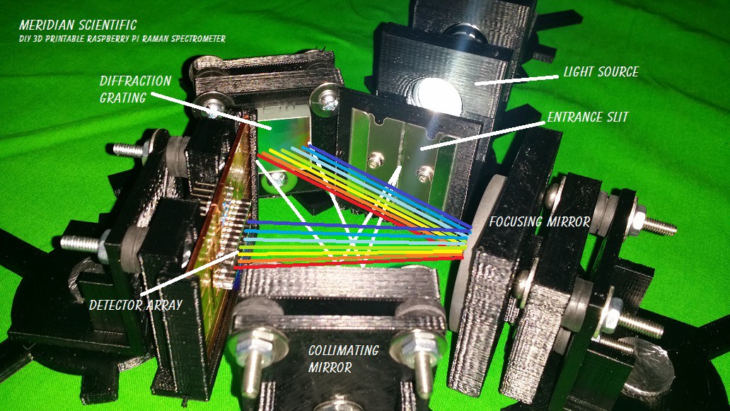
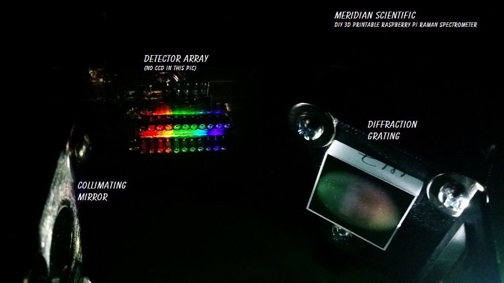
Here's a nice close up.. The light comes in from the left with the flashlight, goes through the entrance slit which acts like a vertical aperture where it's trimmed down and projected as a vertical line on the collimating mirror.. as a result the light is directed into a column onto the diffraction grating in the lower center of this pic.. it's then reflected and diffracted into a rainbow onto the focusing mirror where it's focused across the detector array(linear CCD- Toshiba TCD1304DG)...
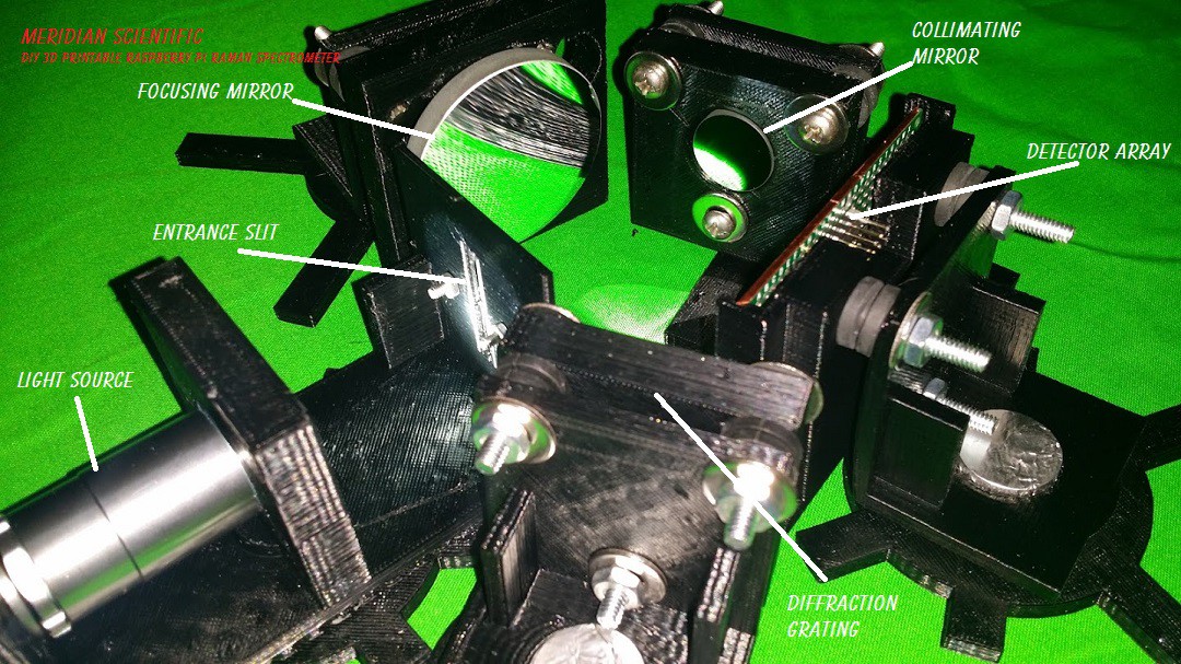
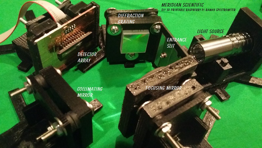
A little closer shot with a slightly better view of my twin razor blade entrance slit and the diffraction grating..
Another angle and illustration of the light path...
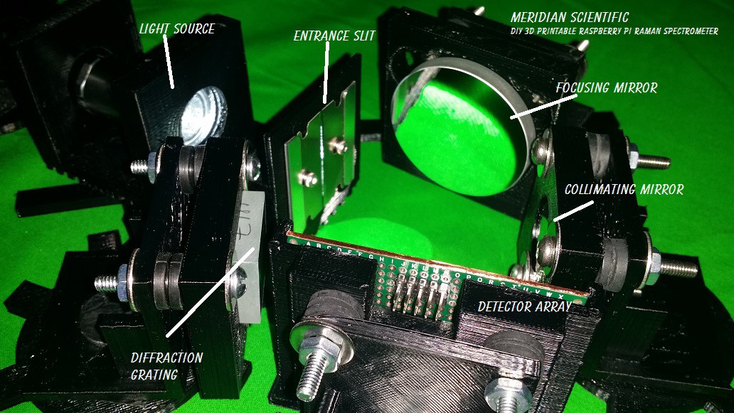
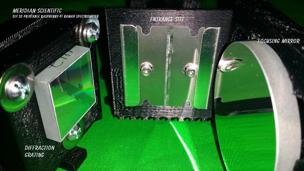
A really nice closeup of the twin razor blade entrance slit, and both the diffraction grating (left), and the focusing mirror(right).
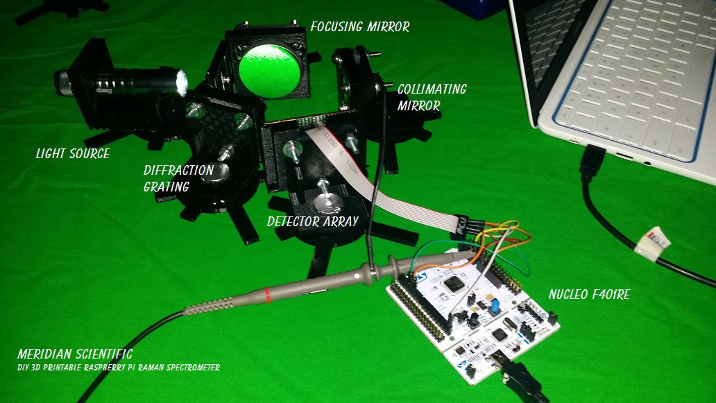
Here's the whole setup with the nucleo hooked up to the Toshiba CCD...
One more angle for good luck.. ;)
And what you've been waiting for... First spectra... I didn't have the CCD installed here because I wanted to align everything first.. But there it is... (You might notice the notch in between the blue-green and the purple where the LED flashlight doesn't emit much light..)
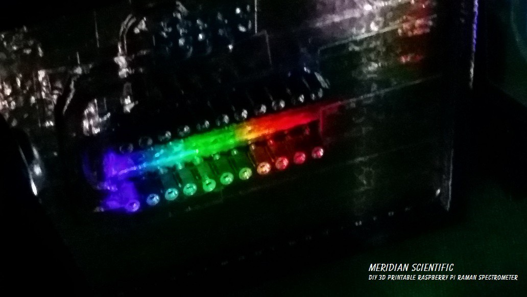
Another angle of the same, with the grating and collimating mirror visible..
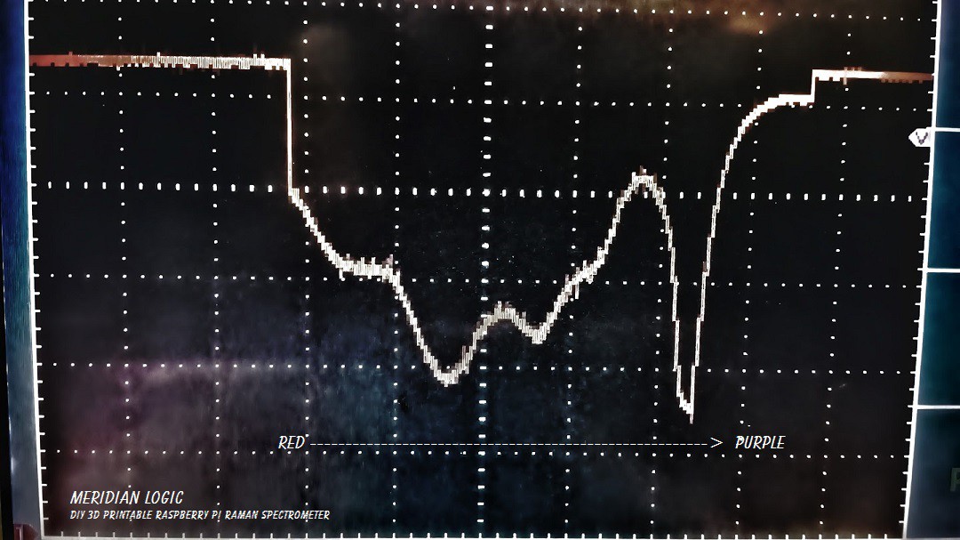
And there's the scope... Bad photo but it clearly shows the notch I mentioned above between blue-green and purple! And you might also notice how little noise it's producing.. =) I might also note, that the scope pictures are inverse values.. So what you see is essentially upside down. In this first picture, you can really tell the LED had a lot in one band of purple not much blue and quite a bit of green and yellow, and about half as much red...
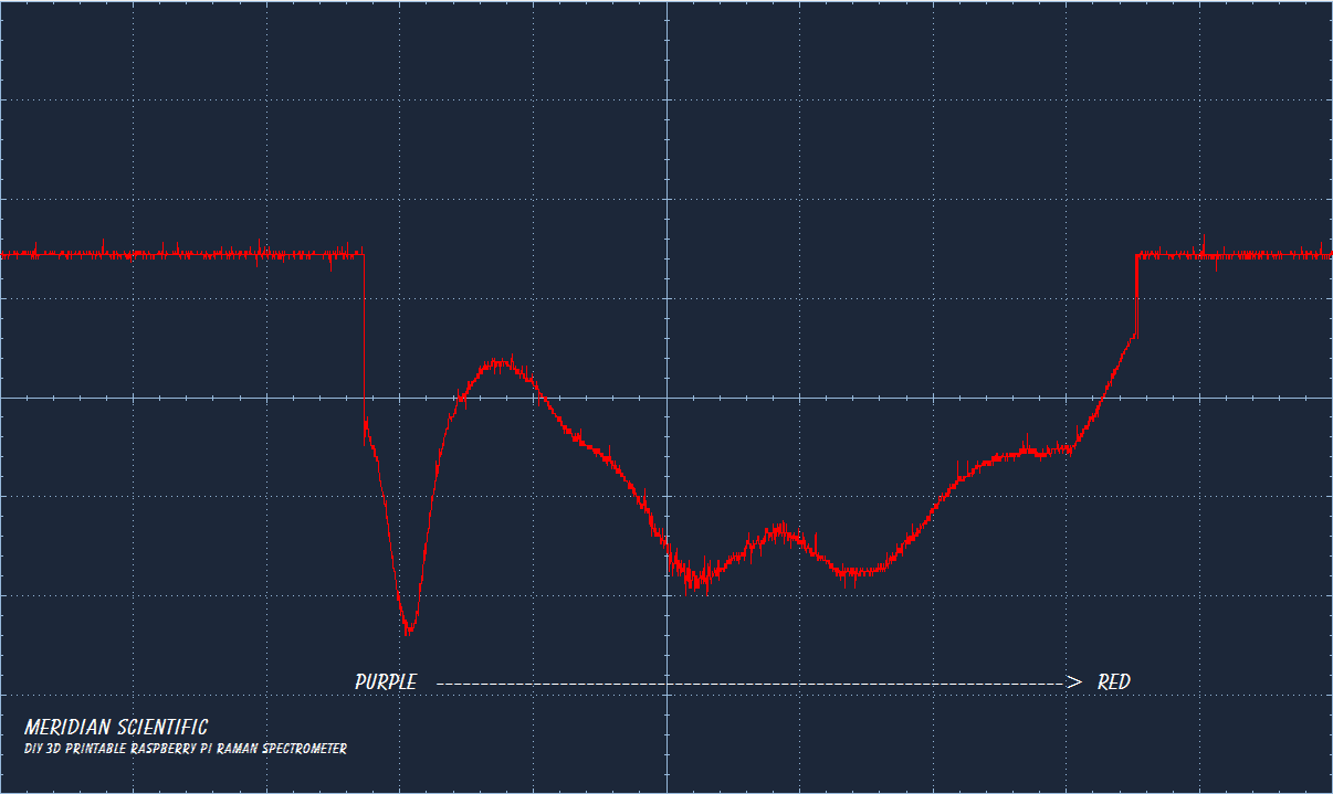
This one goes from red on the left to purple on the right and the others from the PC are the opposite...
Ok.. so here are some better captures from the PC software...
First up... The straight LED light from the flashlight...
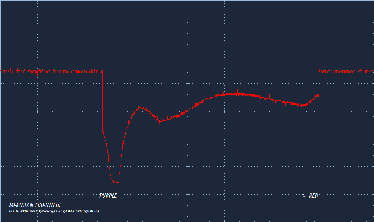
Next up is a piece of clear plastic colored with a purple sharpie..
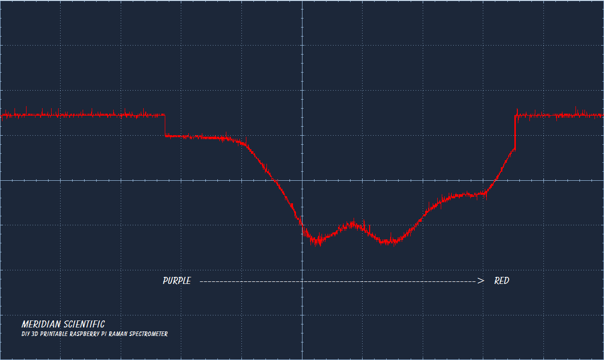
Next we have another piece of plastic colored this time with a yellow sharpie..
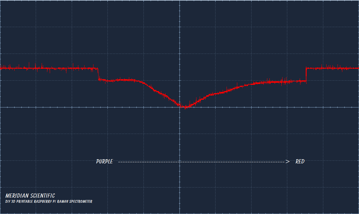
And the same but this time it's green...
So, there you have it... the first round of result with some good spectra! Next step is to get a little more serious with my code... start using the numbers from all of this in my 3d models and hopefully print some stuff up to test with... And more importantly...something better than an LED flashlight to test with... and some better color filters than sharpie colored plastic...not sure why I didn't think ahead on that one...
And especially here... if anyone has any input or suggestions...or just friendly comments and criticism...I'd love to hear it all!

Discussions
Become a Hackaday.io Member
Create an account to leave a comment. Already have an account? Log In.
Are you sure? yes | no
As I progress, I'll make sure I put in more details regarding the spectral orders, etc..Ultimately, I will be doing something similar to what is depicted on this page.... http://www.azom.com/article.aspx?ArticleID=10121 Particularly in this image... http://www.azom.com/images/Article_Images/ImageForArticle_10121(1).jpg
I'd be interested to hear your opinion!
Are you sure? yes | no
Are you sure? yes | no
Are you sure? yes | no
Thanks again, can't wait to get the raman spectra..!
Are you sure? yes | no
Congratulations, this is a huge accomplishment!
Are you sure? yes | no
Are you sure? yes | no