I've more or less completed my first pass of everything from the cart to the 2nd pendulum. I still need to start work on the rails and the linear actuation. To get signals from the 2nd encoder (between the two pendulums) to the cart I plan to use a slip ring.
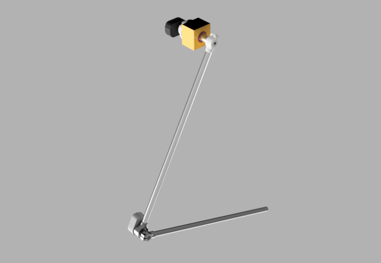
Here's a quick (not especially instructive) render:
And here's a picture that probably makes a bit more sense:
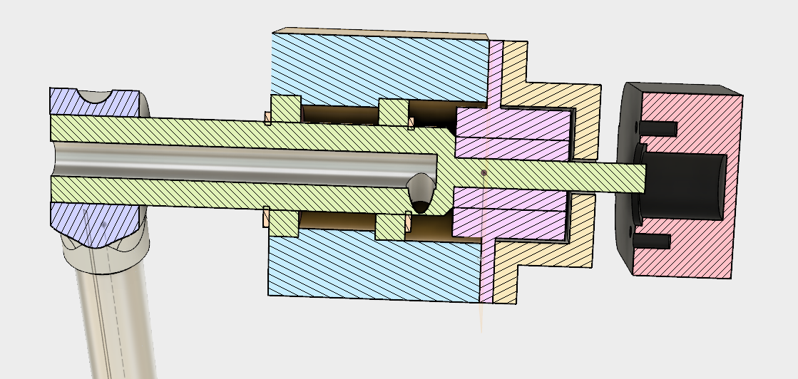
The idea is wires from the 2nd encoder (between the 1st and 2nd pendulums) pass through the hollow shaft (green), then after the bearings (also green), exit the shaft the the hole in the side and enter the slip ring (pink). The orange cap holds the slip ring in place and supports the first incremental encoder (orangey-red). I've still got to flesh out the details of how the encoder is attached, hence its currently floating in mid air.
All of this will sit on the cart, which is going to be a stock V-Slot plate with four v-slot wheels.
The joint between the two pendulums is a similar set up, but without the hollow shaft:
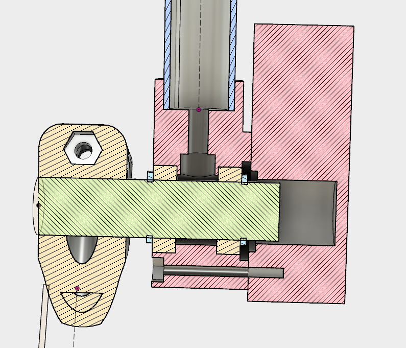
The orange block on the right is the 2nd incremental encoder. The block in the middle holds the bearings, and the shaft is positioned with circlips. The circlips may rub against the outer bearing race so I'll probably put some shim washers in to make sure this doesn't occur. The pendulums are attached using the design I outlined in my previous post.
Discussions
Become a Hackaday.io Member
Create an account to leave a comment. Already have an account? Log In.