 Matias N.
Last time I mentioned I wanted to get into designing a proper PCB for the device. So, since in the proto-board most things were functioning as expected. I decided to go ahead and start designing a PCB in Kicad.
First attempt
I must say I considerably underestimated the difficulty of cramming everything so tightly.
At the beginning I was aiming for a single two-sided PCB where I would mount: Teensy 3.1, OLED screen, battery charger, HC-05 bluetooth module, battery holder, four push-buttons and a power switch. After fighting a lot and going back and forth between different options, I realized it wasn't worth it.
Second attempt
So, I took a step back and decided I would use a simpler approach (after all, all of this started with "I'll just cram everything together with no PCB and solder everything via wires"). So, I started analyzing the main problems with the approach.
First, I realized the main problem was mounting the HC-05 bluetooth (bare module, since I have 3.3V already and does not make sense to regulate from 5V back to 3.3V) next to the Teensy, without wasting space. Since the module is for surface mounting, no other board (i.e. the carger) could be soldered using holes there. The second problem was that the charger module wasn't really intended for soldering to another PCB. Well, maybe it is possible, but the surface it occupies does not make sense. Finally, the 3V battery holder was just huge.
The solution
First, I decided to get rid of the battery holder. The 3V battery will be connected directly via wires (I can wrap the battery in insulating tape and maybe even try to solder wires to it).
Second, I realized the HC05 has almost the perfect size to be mounted on top of the Teensy with another PCB. While I initially attempted to design a PCB so that I would have something like a teensy "shield", I decided to simply do like a "lateral" breakout board. Then, the rest of the device would have a second PCB (where the teensy sits) and where the HC-05 breakout would connect. I could have used a similar design to that of the original breakout (pins on one short end), but this would block teensy's program button. With my approach, the button is reachable (with a little effort).
Finally, with this approach I managed to have the main PCB at 4x4cm, just the size of the battery.
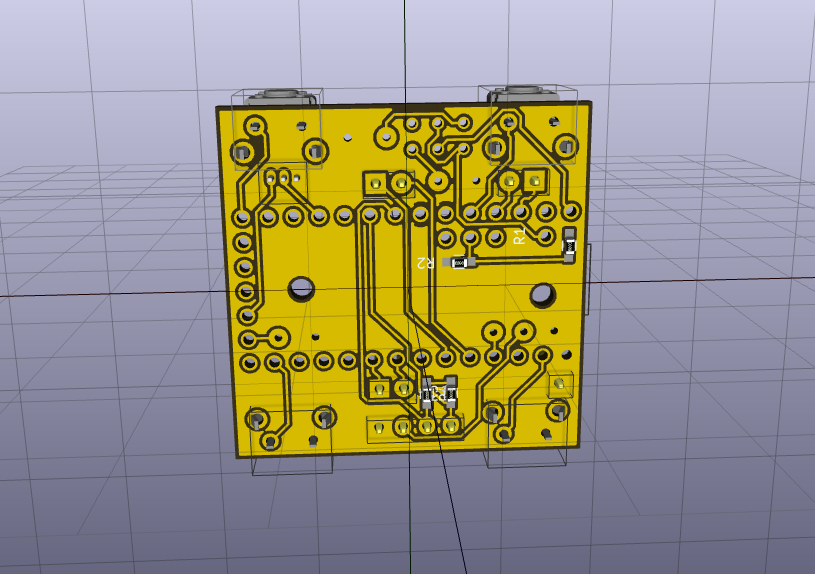
While it took some extra effort, since I had to reassign a lot of pins on the Teensy to allow for more direct paths, I managed to even only use single-sided PCBs for both boards.
Behold the results.
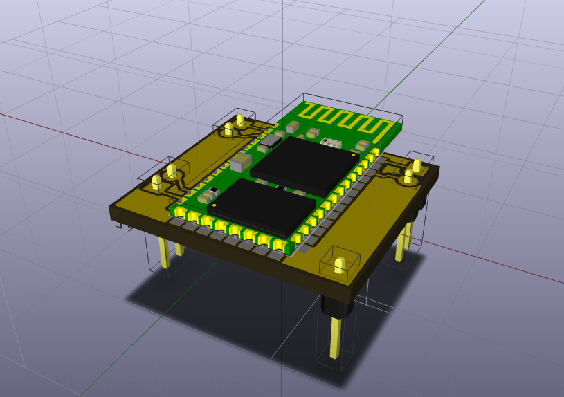
The HC-05 "shield":
The base board:
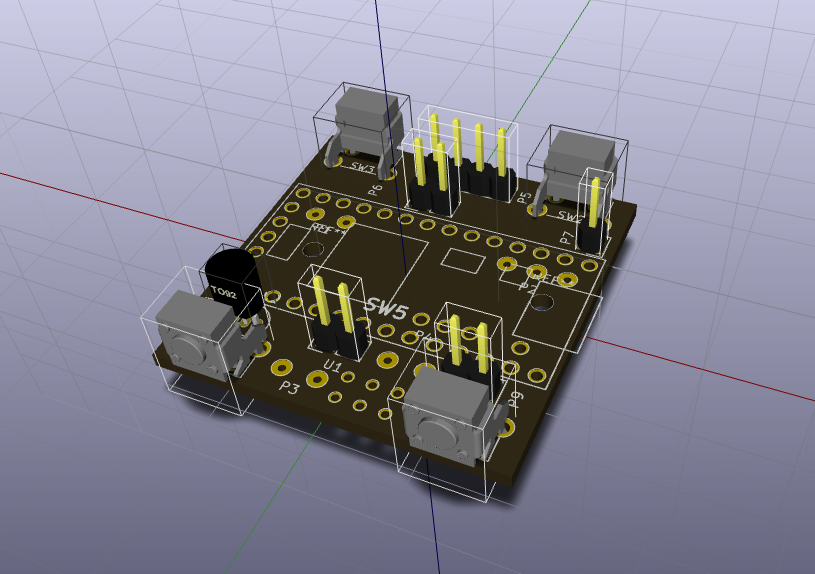
The four push-buttons would be on the top and bottom sides of the device (easier to handle while driving, I hope). I could not find an angled DPDT slide switch 3D model, so I hope it fits. The male pins connect to the HC05 board while the teensy sits in the middle. There are some large pads which are intended to solder the remaining components via wire: charger input and output, hall sensor, RTC battery.
Now, I need to see if I get this manufactured. I hope this PCB makes sense and I have not messed something up which makes it impossible to build.
Discussions
Become a Hackaday.io Member
Create an account to leave a comment. Already have an account? Log In.