Close
0%
0%

Spa Controller

Making an old spa useful again!

Similar projects worth following
In a quest to save money and make an old hot tub useful, I set out to update the ancient electronics controlling the spa at our recently purchased home. The goal was to automate as much of the management as possible since, at the time of purchase, I would need to manually operate everything from the breaker box (which is dangerous if wet!).

Therefore, the primary goals where:
1) Safety. Keep electronics removed from water locations.
2) Let a user remotely & safely operate the pump and heater.
3) Allow scheduled maintenance runs so that the filter could do its thing.

Secondary goals:
1) Let the spa manage its own temperature.
2) Track usage as well as temperature over time.
3) Add safety measures:
- Alert when temp is under 40 degrees F
- Keep temp from exceeding 108 degrees F
- Automatically turn off after running for a specified amount of time.
- Send alerts (text messages) for issues

Back in Feb, my family bought a new house that came with a very old hot tub built into the deck. When I opened it up in May, I was surprised to find that the plumbing was actually still good! However, the controls where an entirely different story. Things where miss-labeled (such as the Heater being called "AC" on the breaker box!), the original controls had been bypassed since they didn't work, and the wiring was a mess. The only way to operate the pump or heater was to go through the house, to the basement, and manually flip the breaker at the electric box. The light does not work at all and the blower's pneumatic button worked ~20% of the time.

I looked around and found that I could buy a new controller for for ~$450 (parts only) but that doesn't count installation and didn't solve my desire to be hands off with the maintenance! After all, it needed to be run a couple hours a day for the filter to work and I didn't want to have to remember to do that each day!

After looking over the disastrous electrical mess, I found that I could add relay's to the pump and heater power supplies as well as improve the accuracy of the existing blower's pneumatic button with very little effort. From there, it was just a matter of outlining my project!

Here is how I broke down my project (keep in mind that the heater, blower, pump, and filter exist in the basement with in-ground plumbing to the outside deck):
Phase 1 - Get the Pump/Heater on a timer.
Phase 2 - Get the water temperature as an IoT device.
Phase 3 - Control the Pump/Heater on relay's and control it through an IoT device.
Phase 4 - Develop a web application to interface with the IoT devices (record temp history, report status, etc).
Phase 5 - Use a MQTT broker for better integration into existing home-automation services.
Phase 6 - New Control panel and relay for blower.

  • 2 × NodeMCU ESP8266 Developer board that has its own usb->serial programmer, voltage regulater, and other parts built in. Used for IoT capabilities.
  • 1 × DS18B20 Waterproof temperature sensor that uses the 1-wire protocol.
  • 1 × Raspberry Pi Runs the Python server and MQTT broker
  • 2 × SPST G8P-1A4P-5VDC Relays that can handle up to 250 VAC at 30A and feature a 5v coil.
  • 1 × 4.7k Resistor Needed for DS18B20 sensor

View all 12 components

  • Phase 1

    Jaron07/25/2016 at 21:19 0 comments

    Phase 1 was to add relays to the pump and heater so that they can be controlled by a microprocessor in the future. For the time being, just having the relay allowed me to use an AC->DC converter to trigger the relays with a 120V timer so I could schedule when it ran (and override that manually when we wanted to use it!).

    Since I didn't want the heater to ever run though without the pump being on, I setup the heater's relay so it could only operate when the pump's relay was on. This was done by using a smaller 2-ch relay shield to power the 5v lines that went to the pump and heater's large relays. The 1st channel provided the power to the pump's relay as well as the power to the 2nd channel. The 2nd channel then was used to power the heater's relay. This way, both channel 1 (the pump) and channel 2 (the heater) have to be on for the heater's relay to switch on.

View project log

Enjoy this project?

Share

Discussions

nodemcu12ecanada wrote 08/22/2020 at 11:57 point

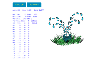
A very inexpensive NodeMCU controller, real time clock, digital temp sensor and relays can accomplish all of the above. Monitor and control from a web page instead of an app. Upload program changes wirelessly. Send data to a cloud spreadsheet viewable from anywhere. Monitor and control from anywhere using MQTT. I use 6 of them to save $1,000/year.

https://sites.google.com/site/nodemcu12e/

  Are you sure? yes | no

Similar Projects

Does this project spark your interest?

Become a member to follow this project and never miss any updates