 willbaden
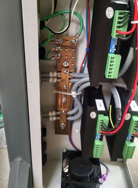
The Stepper Drive enclosure is separate from the controller enclosure. It started life as a heater controller that had something to do with commercial printing. It was sourced from the same place as the printer used as the Y axis gantry. The stepper power supply is a 48V MeanWell. 220V is fed in on the top side from the power switch. (fuses are in series between the switch and the power supply)
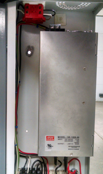
This feeds a terminal strip that breaks out to the four stepper drivers. (a fuse is in series between the power supply output and stepper drivers)
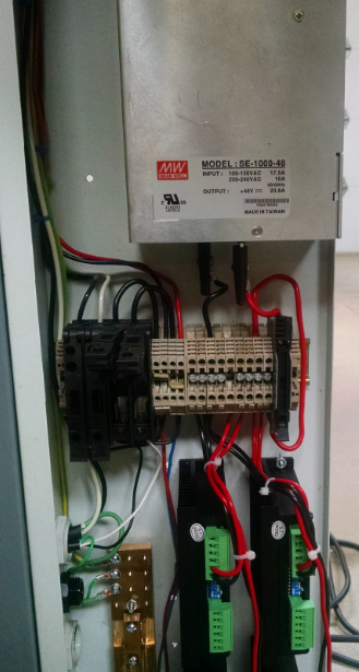
The photo above is early pictures that does not include an estop circuit that disables the stepper drivers. I am a bit concerned that the enable input on the stepper drivers is active high to disable. I would rather it be active high/low to enable the drives. So if power is lost to the input, they would shut down. Lesson learned on using M452's. The terminal blocks were sourced from another industrial controller box that was going to be thrown away.
The ground bar to the left acts as the main safety ground and as a sink for noise as the shielded cable is fed into the box.
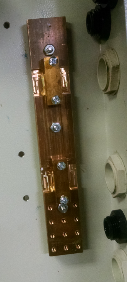
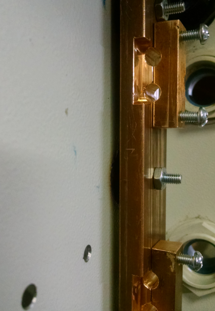
The shielded cable is fed through the clamps with the shield exposed. The screws clamp around it to drain any noise that could be coming from the outside. The brass bar stock for these were used as door handles prior to being machined and repurposed as the grounding bars. The three studs that stick out to clamp the ground bar to the enclosure are welded on from the backside.
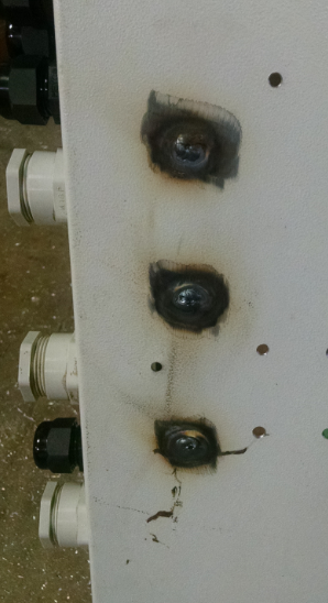
Below is a pic of the stepper cables being fed through the ground bar.
The cover to the enclosure originally had a window for the controller interface. This was closed up with some scrap steel that was cut with the plasma table.
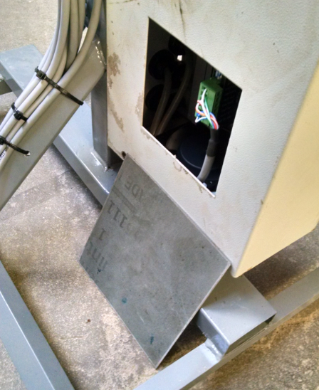
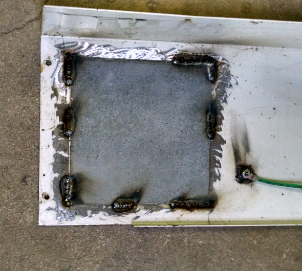
Also seen in the above photo is a ground stud that ties the ground bar to the enclosure cover.
Discussions
Become a Hackaday.io Member
Create an account to leave a comment. Already have an account? Log In.