 Ted Yapo
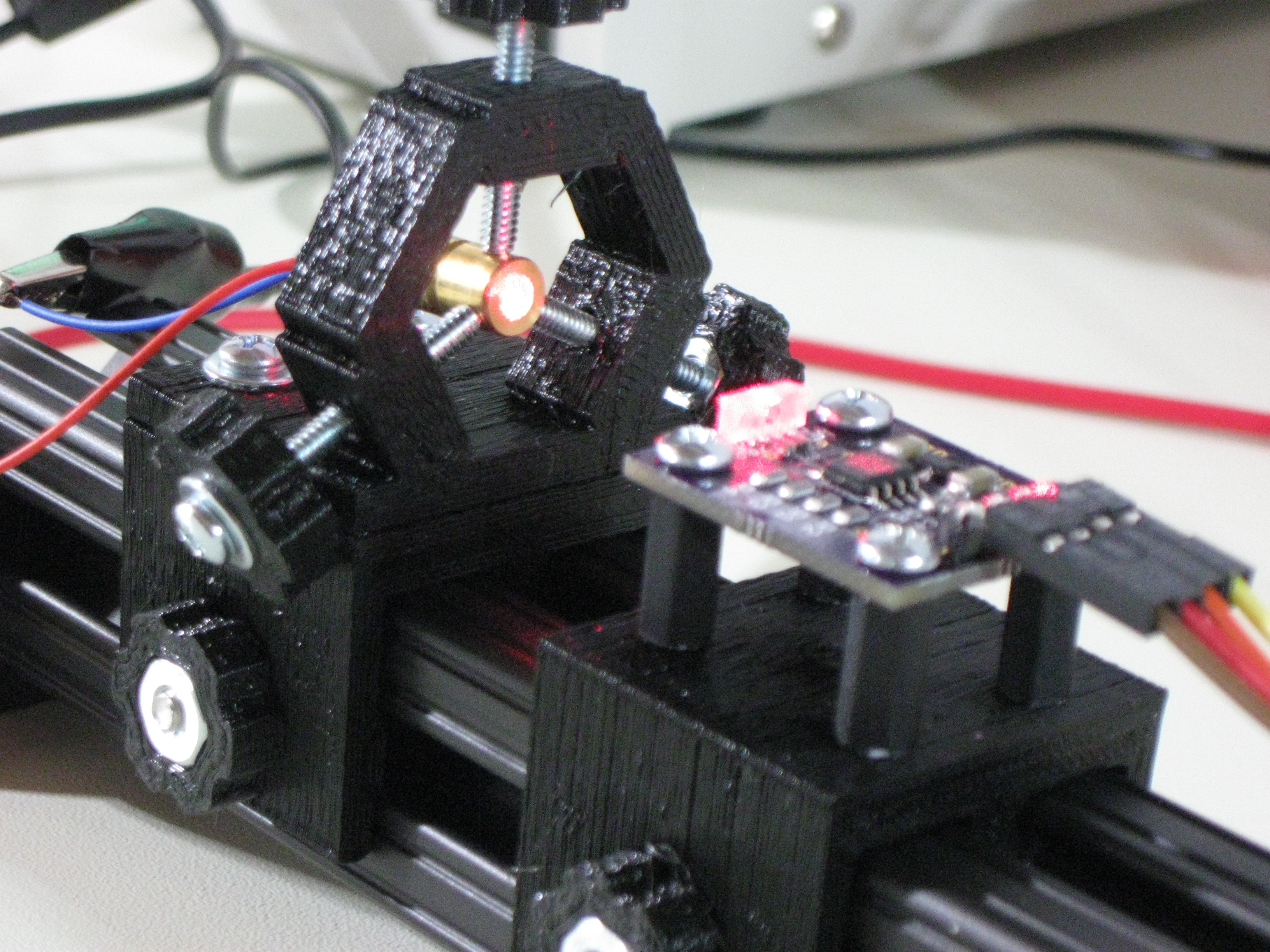
I decided to design some rudimentary optical rail mounts for positioning devices during test. This makes for easy adjustment of distances and angles, and allows insertion of other optical elements such as filters or lenses as required. Here's a cheap ebay laser diode module in a ring-mount "destroying" the sensor.
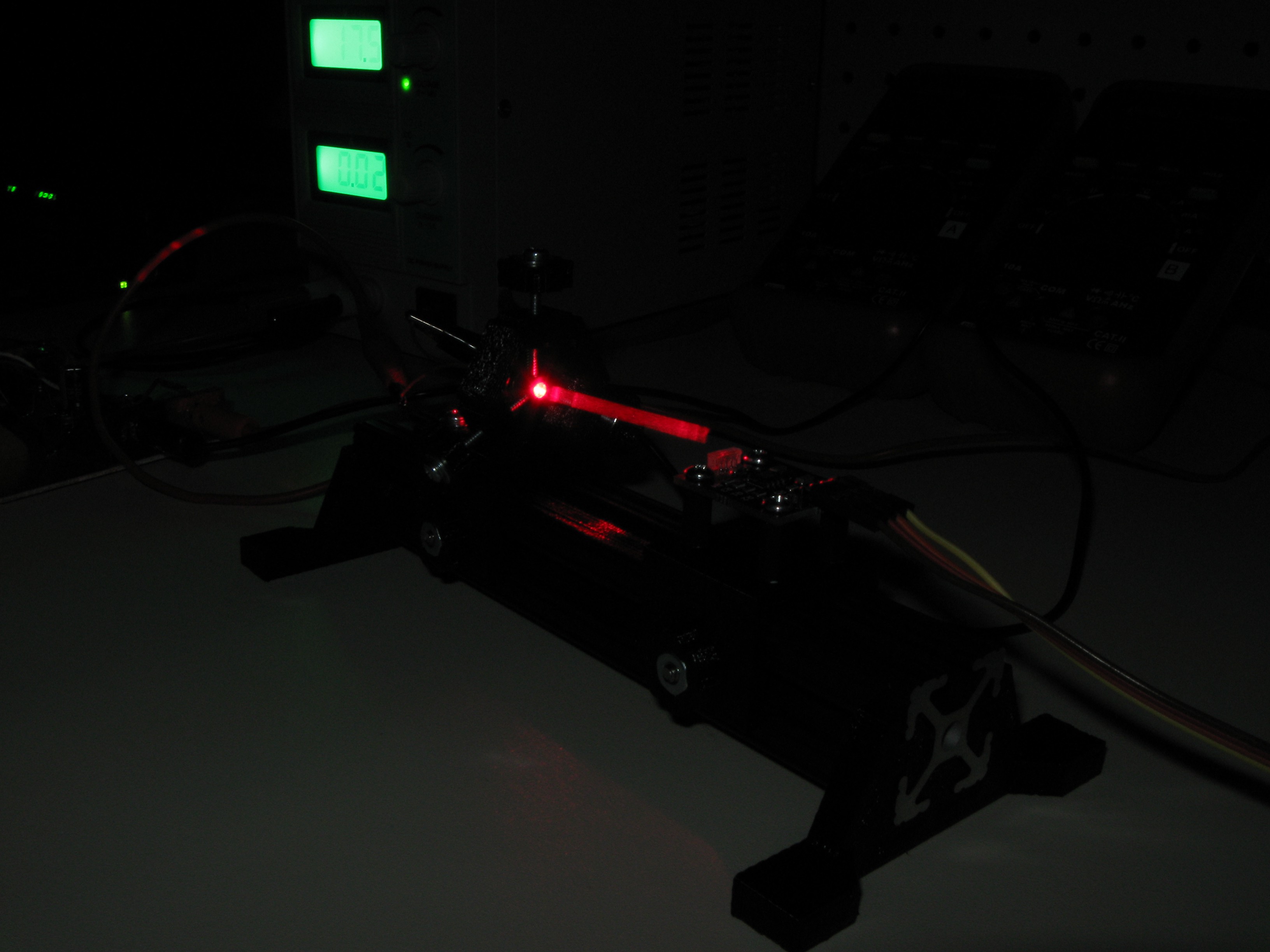
(no sensors were harmed in the creation of this log; see the last section for the photographic trick).
For the rail, I decided on sections of 1" 8020 aluminum extrusion. I also have samples of MicroRAX (10mm), MakerBeam (10mm), OpenBeam (15mm), and 2020 (20mm) extrusions, and the 1" stuff seemed about the right size and rigidity for a rail. Here's a close-up of the sliders:
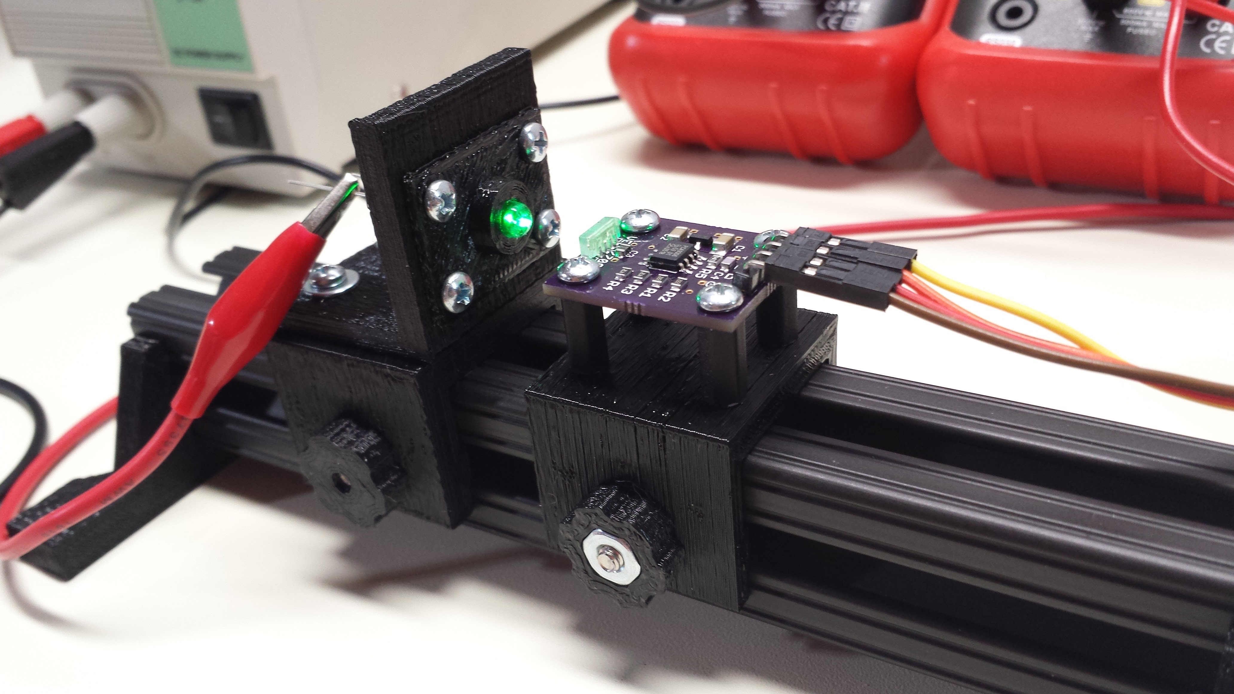
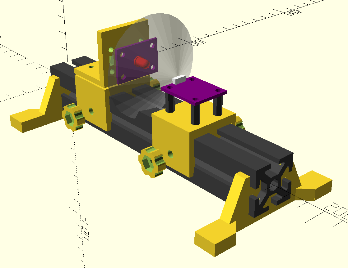
The mounts have "floating" inserts in the side rails that clamp down solidly with the thumbscrews. The thumbscrews on the right are the final design; the slider on the left was too thick for the screw length. Shown are a mount for the VEML7700 sensor carrier board and one for LED test boards, described below. I printed a "fake" board to mount 5mm LEDs for initial tests. The next image shows how the LED boards (left, purple) will mount on the carrier. The transparent cone represents the half-sensitivity angle (55 degrees) of the sensor. I have some black-oxide steel screws that would cut down stray reflections, but they make these parts even more difficult to photograph.
Shown here is the design for the laser mount. It uses three long screws with nuts embedded in the hexagonal frame to allow positioning of the laser. This mount could also hold small optical components.
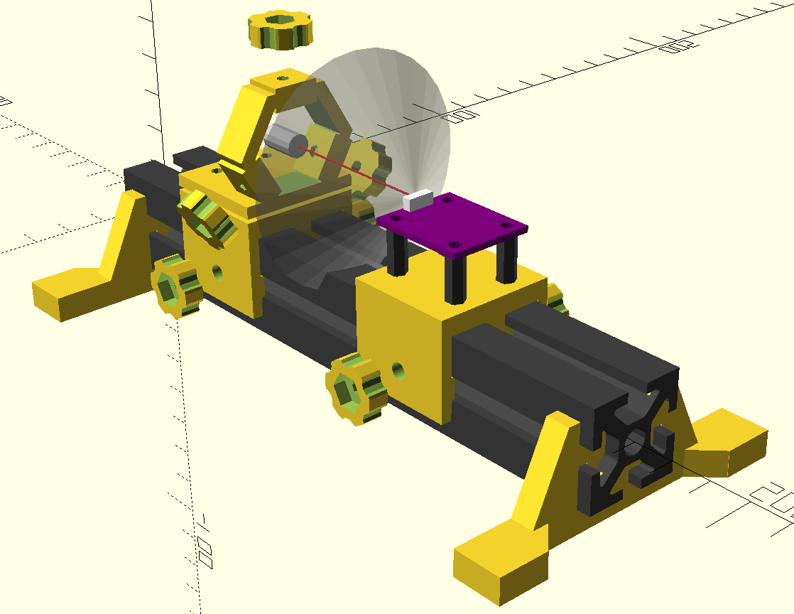
Here it is with a laser diode mounted. I ordered some rubber screw protectors to tip the set-screws with, but they haven't arrived yet. Two of these rings would provide a rough adjustable-angle mount for longer devices (like frequency-doubled 532nm green laser modules).
I've started a GitHub repo for these optical rail components; I'm so happy with how convenient they turned out to be, that I'm going to make some more. There's nothing in the 8020-optical-rail repo as I write this, but after I clean and organize the files a bit, I'll commit this stuff there (MIT License) for people to play with.
LED Boards
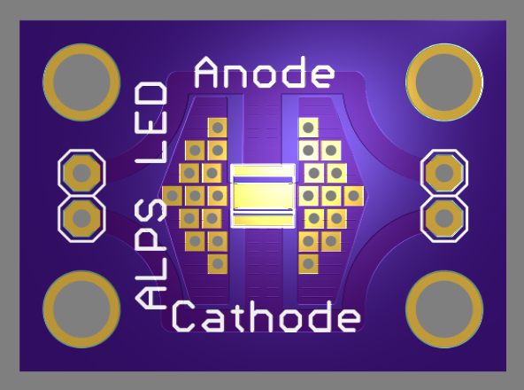
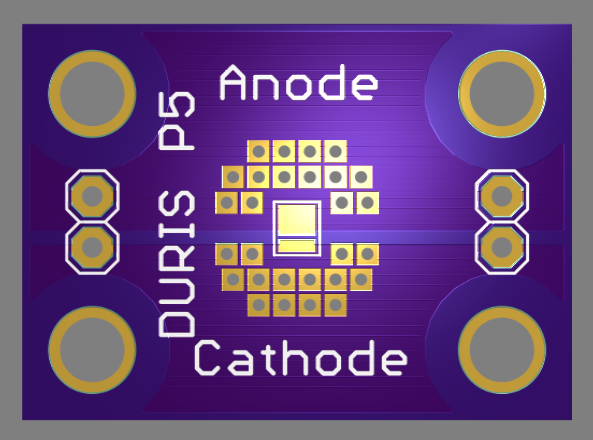
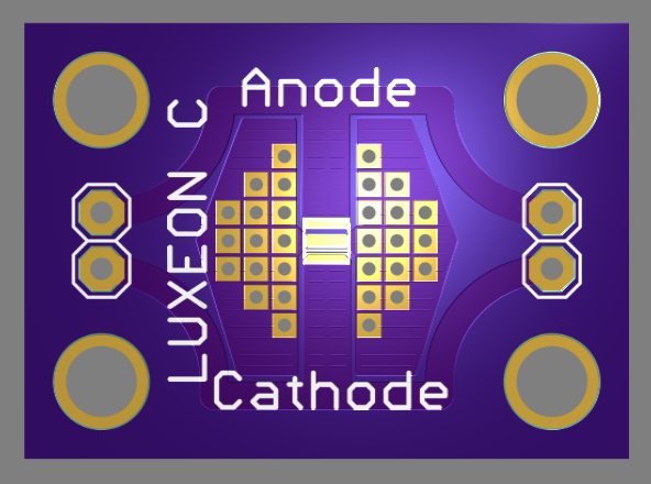
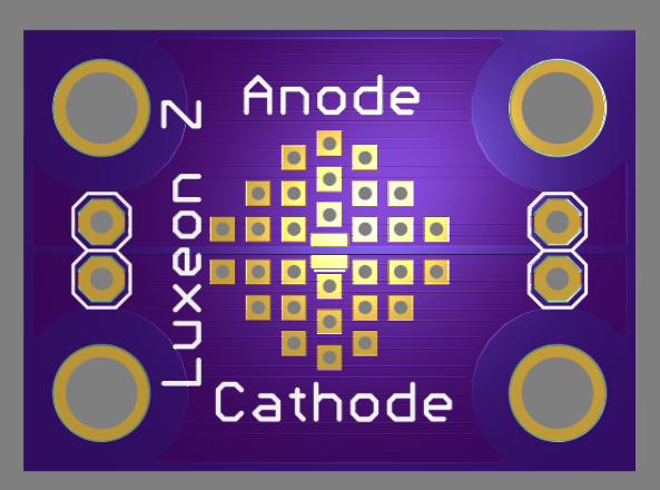
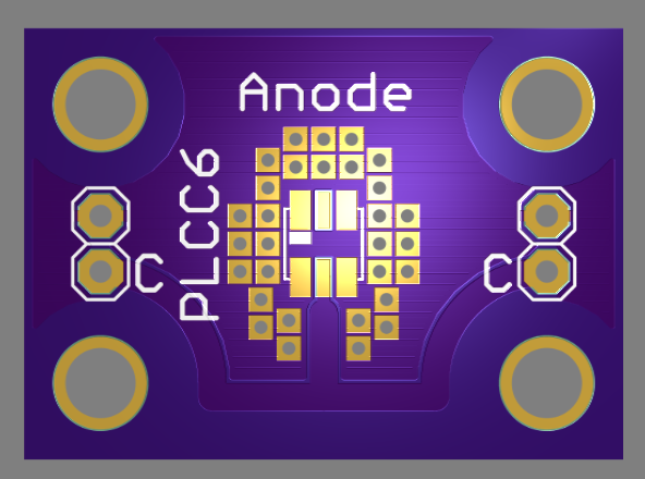
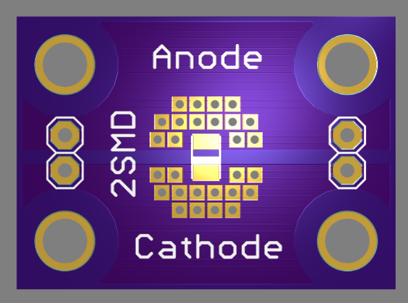
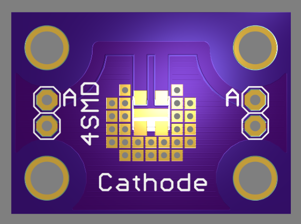
Unfortunately, most of the LEDs I am interested in testing are in unique surface-mount packages. Below are the designs for carrier boards that I've completed so far (these are all being made at OSH park now). I've included some large copper areas and vias for heat transfer, as well as an area on the back of the board for a small heatsink, although I expect to only run them at high currents for brief tests.
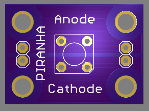 Piranha / Super-Flux
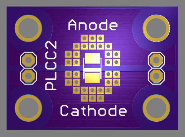 Würth 150141GS73100
SunLED XZM2DG45S
Next Steps
These boards are on order from OSH Park, and once they come in, I can start measuring some of these LEDs. I'd like to explore some of them before settling on hardware for the analyzer, because I'm sure I'll learn something that will improve the design.
Photographing Laser Beams
Here's an old lab trick for making low-power beams show up in your photographs of optical prototypes. Set a first-curtain flash sync on your camera, and use an exposure of several seconds in a dark room (you may also have to stop down the aperture and/or reduce the ISO speed). This will cause the flash to fire at the beginning of the long exposure to photograph the equipment. After the flash has fired, move a piece of clear plastic (overhead transparency film works well) rapidly and evenly along the beam path several times to expose the beam. Here, I used an opaque card and put it in the beam before the flash fired to illustrate the technique:
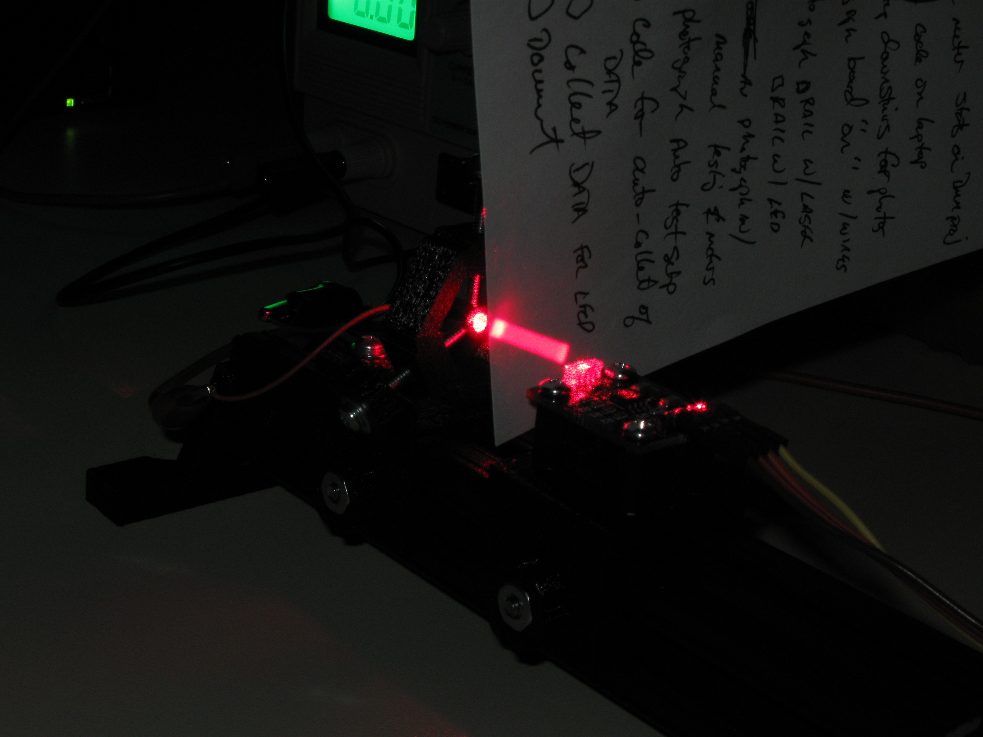
Do I have to tell you not to do this with powerful lasers?
Discussions
Become a Hackaday.io Member
Create an account to leave a comment. Already have an account? Log In.