 Ted Yapo
I was recently humbled to learn that this project was chosen as a semifinalist in the Automation round of the 2016 Hackaday Prize. I'd like to thank everyone associated with Hackaday for making this project possible, and of course for selecting it. The truth is, I would probably have never started this project without the hackaday.io site, as this is basically a spin-off roughly inspired by some of the comments on hackaday.com when #TritiLED was discussed on the blog. I wasn't sure what to expect when I started putting projects on here, and it's been a pleasant surprise to find that it somehow moves projects forward. Thanks, really.
That reminds me - this project was discussed on the blog about 48 hours ago. Thanks to [Brian] for the exposure and kind words in the write-up. As usual, the comments have provided some interesting feedback and ideas; I'll address some of them in this log entry.
LED Stuff vs. Temperature
[rnjacobs] asked if the temperature dependence of the LED characteristics could be measured with this setup. I was aware of the temperature effects before starting this project, but a bit daunted by the prospect of determining the LED die temperature. I had thought of measuring ambient temperature or mounting a thermistor in close thermal contact to the LED thermal pad (when available), but this didn't seem too satisfying. I also thought about the various available sensors - integrated I2C or SPI sensors, thermocouples, thermistors, diodes, IR thermometers ... wait, diodes? The LED is a diode with a repeatable, if unknown, temperature dependence. Maybe the LED can be used to measure its own temperature. Here's the plan:
1. Calibrate the LED as a temperature sensor. I've made thermometers from 1N4148 diodes before: their Vf changes about -2 mV/K. For reference, the Luxeon Z LED lists -2 to -4 mV/K. I don't think it's safe to assume a linear temperature dependence over any significant range, so the Vf vs T curve probably has to be calibrated over the entire range of interest. The idea would be to choose a low forward current, say a few hundred uA, that produces a reasonable forward drop but doesn't cause appreciable self-heating in the LED. The variation of Vf with temperature can then be calibrated by measuring it at a set of known temperatures measured with a known sensor in thermal equilibrium with the LED. The expensive way to do this is by setting test temperatures in a thermal chamber, but I've used a much cheaper method before for similar tests, as discussed in cheap temperature sweeps. To get a set of calibration data for the LED, it would be coupled to a large thermal mass along with a temperature sensor - maybe stick both of them in a cup of sand. The thermal mass is then heated above or cooled below ambient temperature and allowed to equilibrate. Once the temperature has stabilized, the mass is insulated (for example, by wrapping in foam), and allowed to slowly drift back to room temperature. As the temperature drifts, data for the LED's Vf vs temperature can be collected. Now, the LED is a temperature sensor.
2. Find the thermal time constant of the LED-die-to-ambient. Since we will calibrate the LED as a sensor only for a fixed, small forward current, we can't use Vf measurements at arbitrary currents to infer die temperature. Instead, we need to take measurements of Vf and optical output at the arbitrary test current, then switch to the small calibrated current to measure temperature. Of course, in the time we've taken to switch current and make the measurements, the die has cooled off somewhat. It may be possible to estimate what the initial temperature was by measuring the temperature at a series of times, then extrapolating backwards. A similar method is used by forensic examiners to determine time of death by measuring body temperature over time.
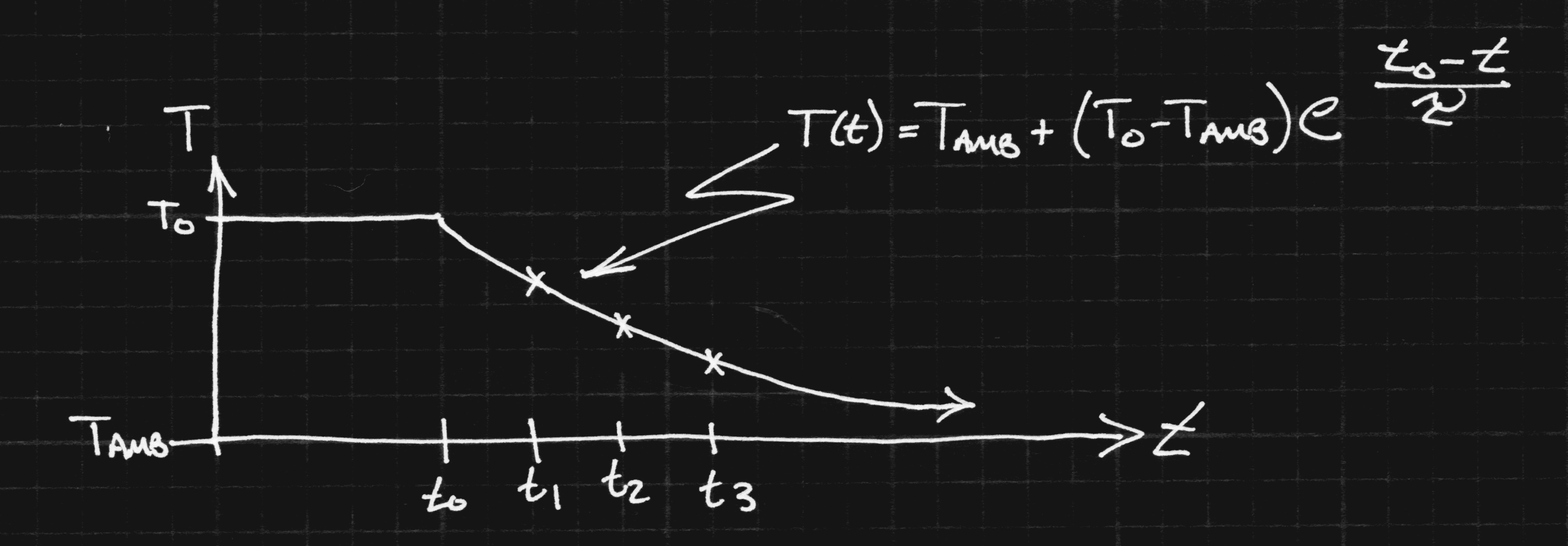
Of course, this is an idealized model; the time constant for the die-case coupling is likely to be much shorter than that for the case-pad, pad-heatsink or heatsink-ambient, and the curve won't be a simple exponential. It will probably take some real measurements to see how quickly the die cools off, and if this idea can be used to improve estimates of die temperature at the test current.
3. Find some way to control the LED temperature. I have made less progress with this idea. Once you can measure the die temperature, though, you should be able to control it. Maybe you can heat the LED through self-heating for large currents, then supplement with a thermally-coupled power resistor for lower currents. On the cold end, the same technique might be used, with the ambient temperature held low with dry ice.
4. Everything else. Obviously, there are a number of things to be worked out before such a scheme could be made practical. But, I think the LED itself can probably be used to estimate die temperature as a first step. At the very least, the Vf at a small nominal current can be measured before/after each test current to verify that the test points are all at similar temperatures. This would eliminate one of the issues with the existing analyzer - you don't know for sure how much of the measured efficiency loss is due to elevated temperature. I've run experiments sweeping the current low-high and high-low, and both produce similar curves, but the thermal time constant might just be short enough to fool this test.
Lumens/Watt vs LED Cost / Lumen
There are a few conclusions you can draw from the efficiency curves I've been measuring. I've looked at about a dozen LEDs so far (and I'll write them up - briefly - in the near future), but I've got the most mileage with the cyan Luxeon Z, so I'll wrap this discussion around that data. I've re-plotted the efficiency curve as a function of luminous flux (aka brightness) here:
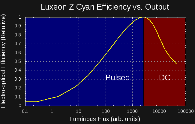
The LED shows a maximum efficiency when outputting around 2500 Arbs (uncalibrated arbitrary units). The graph is divided into two sections on either side of this peak. If you want less than 2500 Arbs of brightness, you're best off using PWM to drive the LED with the current of peak efficiency. Modulo any switching losses, you can achieve the optimum efficiency for any average brightness below 2500 Arbs. This is the regime that #TritiLEDs fall in. If you want more than 2500 Arbs of brightness, you have no recourse but to use DC and either accept the reduced efficiency that comes with higher currents, or buy more LEDs and drive them closer to the efficiency peak.
So, why doesn't everyone just do that? Here's the same plot with the LED Cost / lumen of output added:
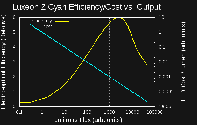
Since the LED cost is fixed (one unit), the cost/lumen curve is a straight line. But, note that the flux and cost/lumen axes are both logarithmic. The LED cost/lumen at the efficiency peak is around 12x greater than at the rated current for this LED, while the efficiency is a little more than 2x greater. You can buy 12 LEDs to get the same light as a single LED but use half the energy. This trade-off only makes sense in certain circumstances, for example, high-performance battery-powered devices. But, for these type of applications, this knowledge can really enhance performance.
It's the other end of the curve that really offends people's sensibilities. The initial response to the PWM-for-efficiency scheme is: "just use an LED and resistor for low DC current" - it's what I thought, too. As an example, consider generating 1 Arb of light with this LED. If you use DC, it takes more than 10x as much power as if you use PWM generating 2500 Arb light pulses at 1/2500 duty cycle.
The more subtle question is why would you possibly use a 500mA LED capable of outputting 30,000 Arbs to generate 1 Arb of output? The answer to this lies in the driver circuit, not the LED itself. Generating small, efficient current pulses isn't easy: inductors get large and inefficient, and/or pulse times become small and difficult to accurately control. As a result, larger LEDs are required to keep the driver within the constraints of the rest of the circuit: large LEDs can be driven with larger current pulses generated with smaller inductors and longer pulse widths.
Arbs vs Actual Units
I thought at first that relative intensity measurements would be sufficient for this project. While they're good enough to measure the relative efficiency of a single LED, they can't easily be used to compare LEDs. The problem is that the optical coupling between the LED and detector will vary from LED to LED, and the detector will intercept a different fraction of the total output for each LED package. The usual way to eliminate this coupling dependence is to use an integrating sphere. I have half a kilo of barium sulfate sitting on my desk to mix a highly reflective paint and two hollow styrofoam hemispheres coming in the mail to make a sphere. I'll be describing the sphere in upcoming build logs.
For now, the units will still be arbitrary, but they'll be the same arbitrary units between LEDS.
Discussions
Become a Hackaday.io Member
Create an account to leave a comment. Already have an account? Log In.
Hey Ted Yapo! Congrats on begin a semi-finalist man!
Are you sure? yes | no