Close
0%
0%

Chronio

Low power Arduino based (smart)watch

Similar projects worth following
Chronio is an Arduino-based 3D-printed Watch. By not including fancy Wifi and BLE connectivity, it gets several months of run time out of a 160mAh button cell. The display is an always-on 96x96 pixel Sharp Memory LCD. If telling the time is not enough, you can play a simplified version of Flappy Bird on it.

DIY watches often consist of a pcb and screen wrapped in duct tape. I wanted to change that by designing a 3D-printed case. It is closely oriented on the Pebble Time.


Hardware

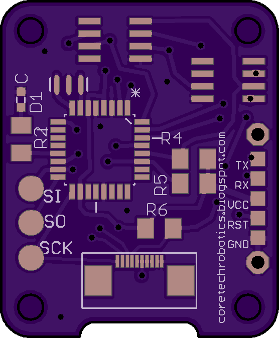
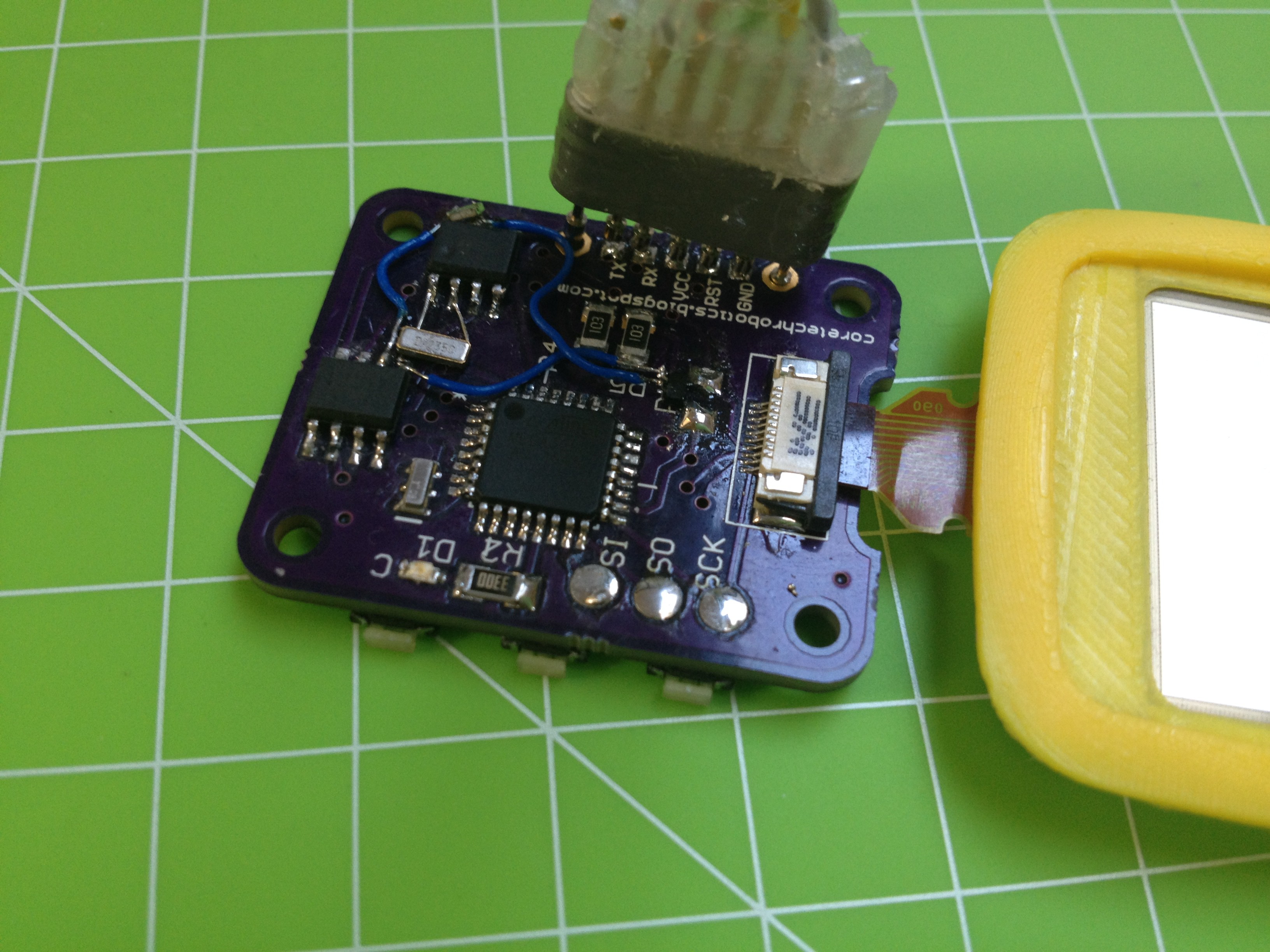
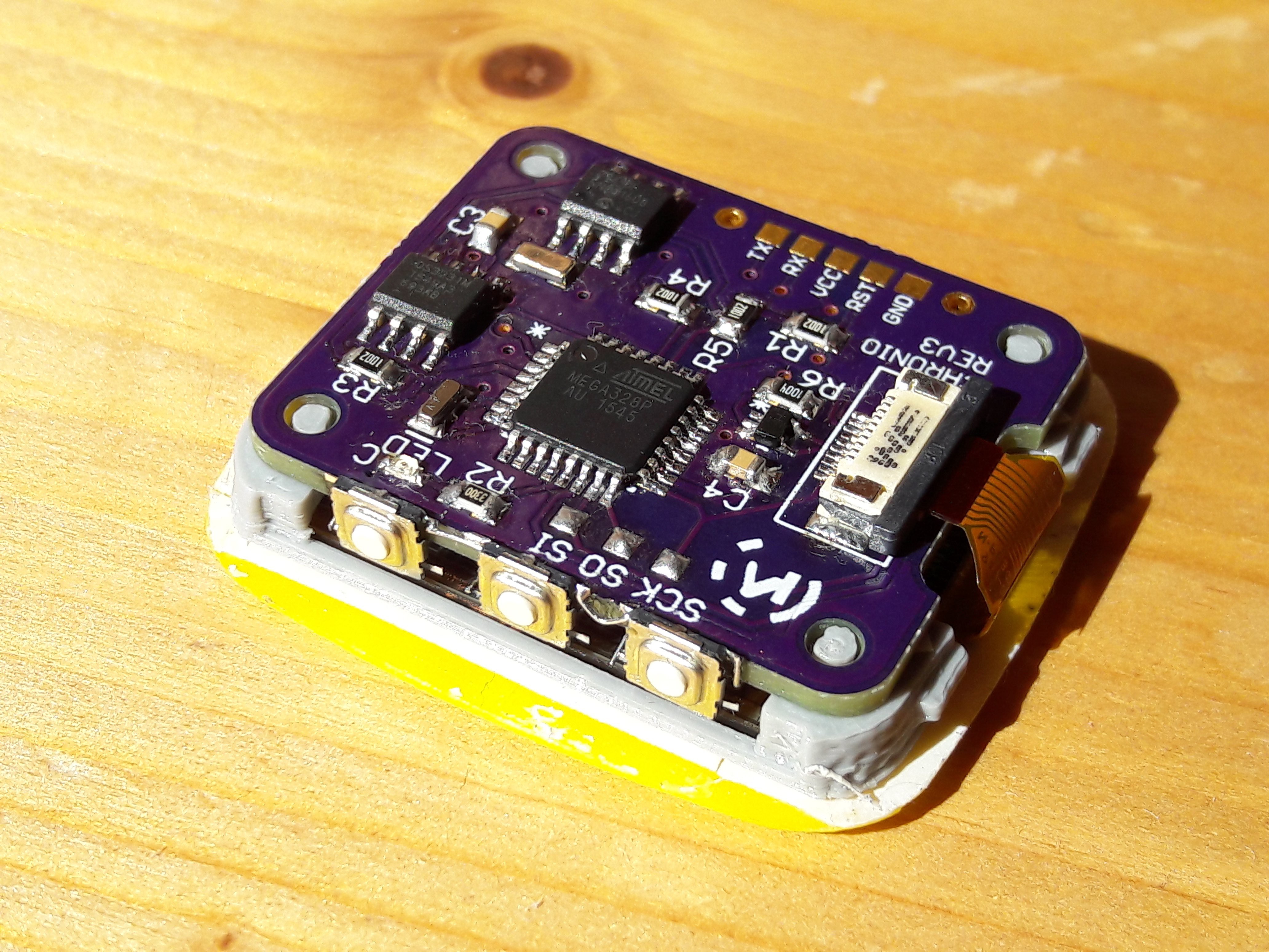
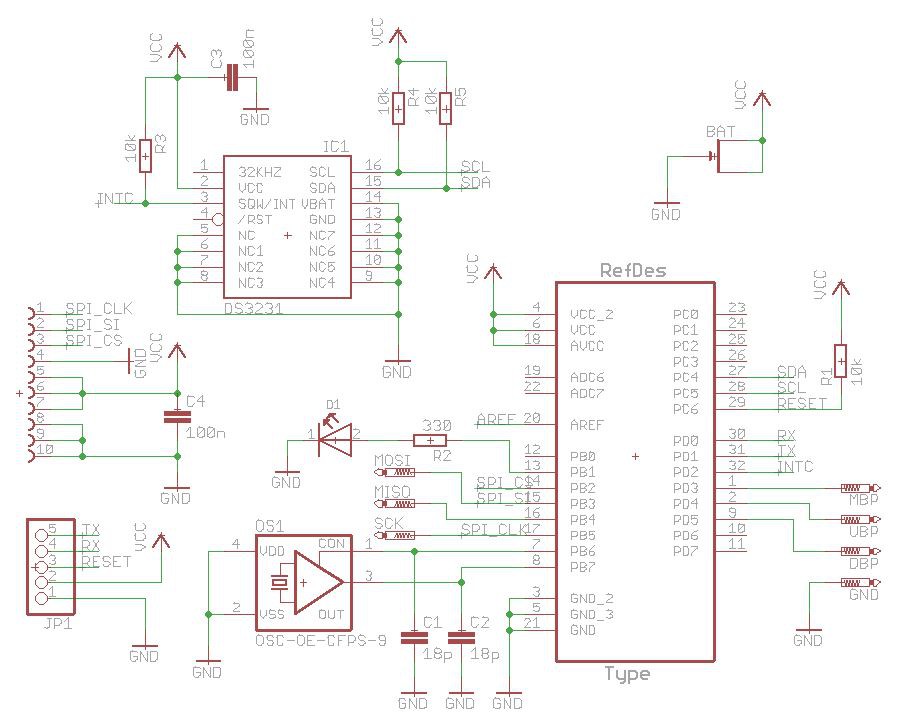
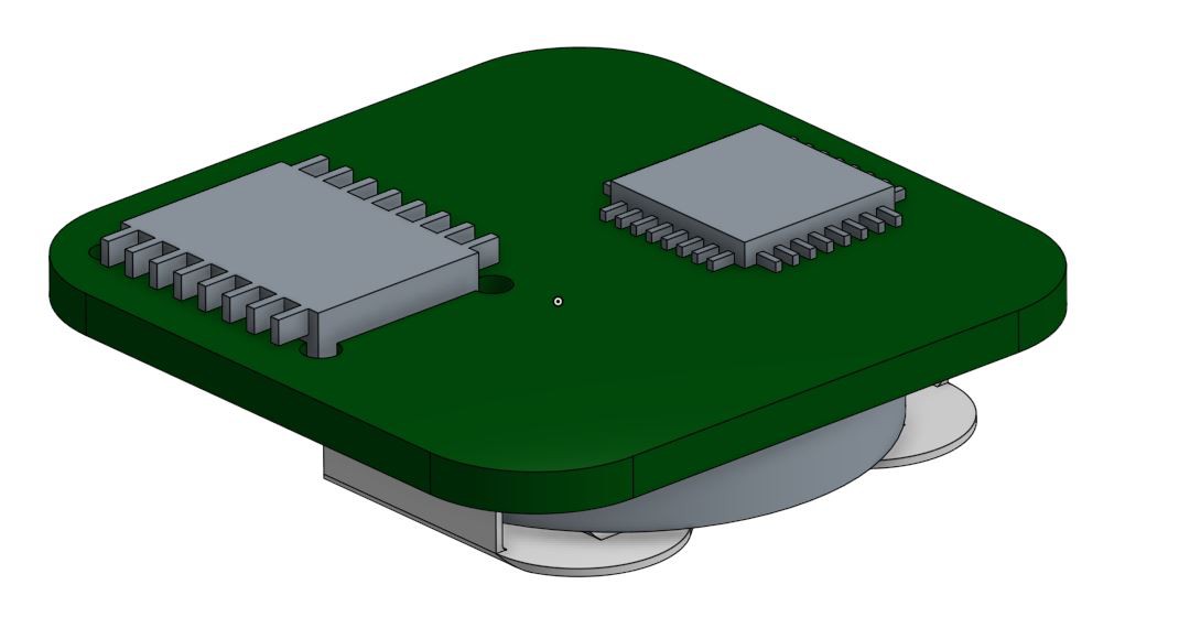
  • Microcontroller: Atmega328p with Arduino bootloader
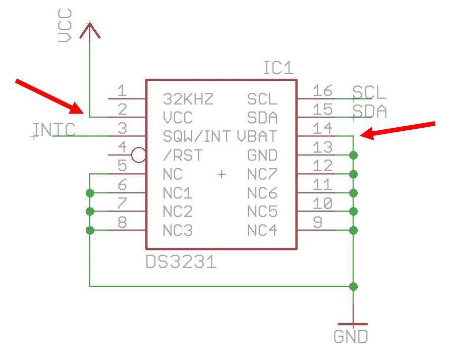
  • Real Time Clock: Maxim DS3231 (<2min per year deviation)
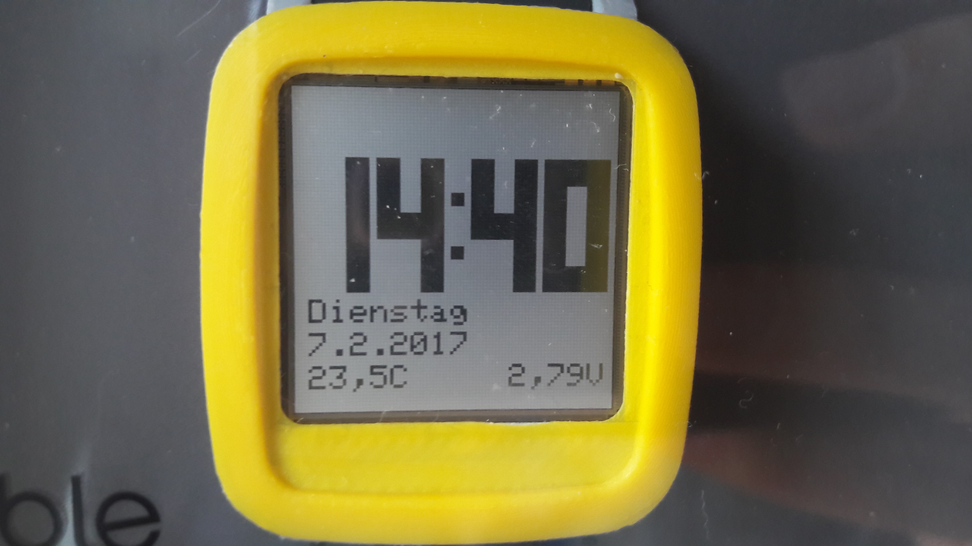
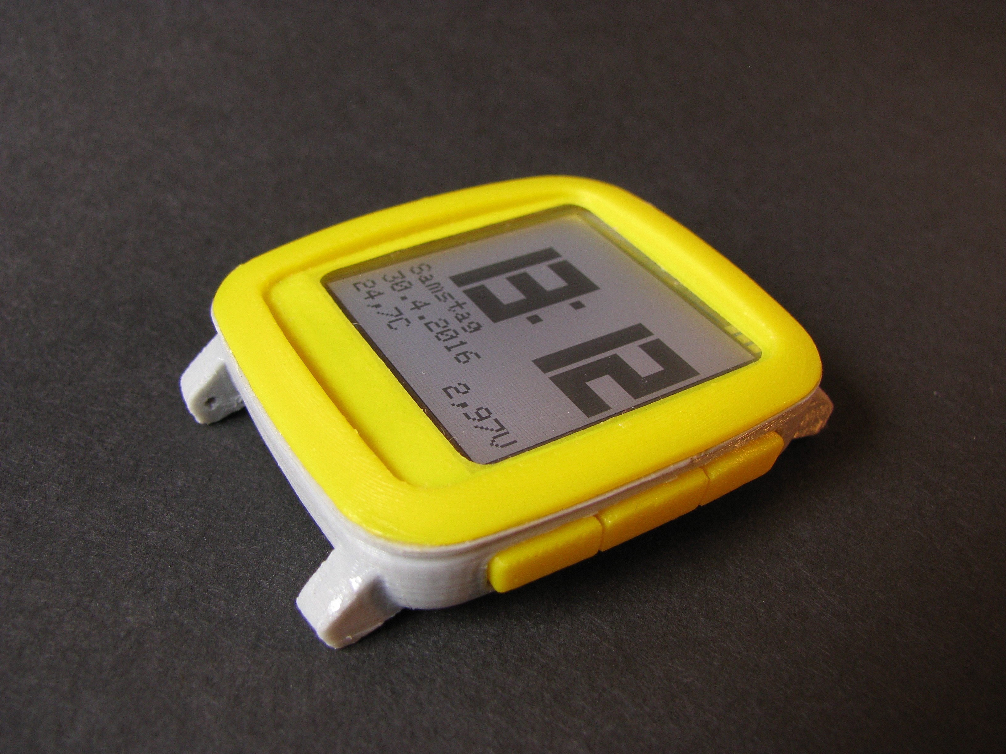
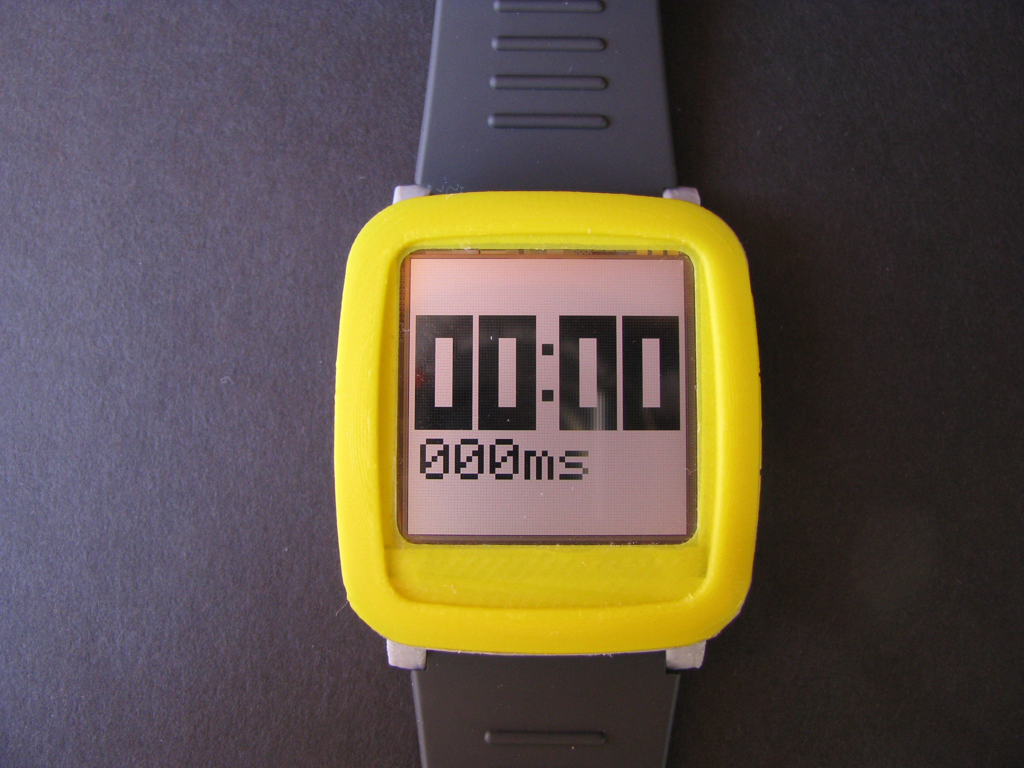
  • Display: 96x96 pixel Sharp Memory LCD (LS013B4DN04)
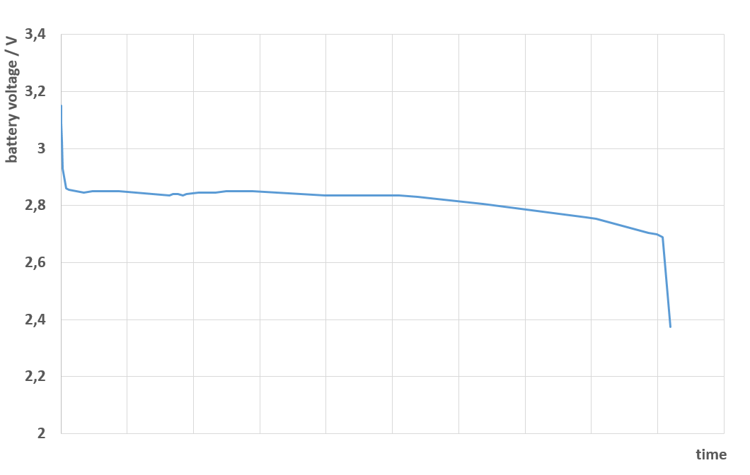
  • Battery: CR2025 160mAh coin cell

Features

  • The ATmega is in Sleep mode for most of the time and only runs once a minute to update the time or if a button is pressed. This reduces the current consumption to 2uA. Sady the display needs a certain pulse every second, which requires a complicated additional circuit. Because of this the current consumption is around 20uA. This still makes for around half a year of battery life.
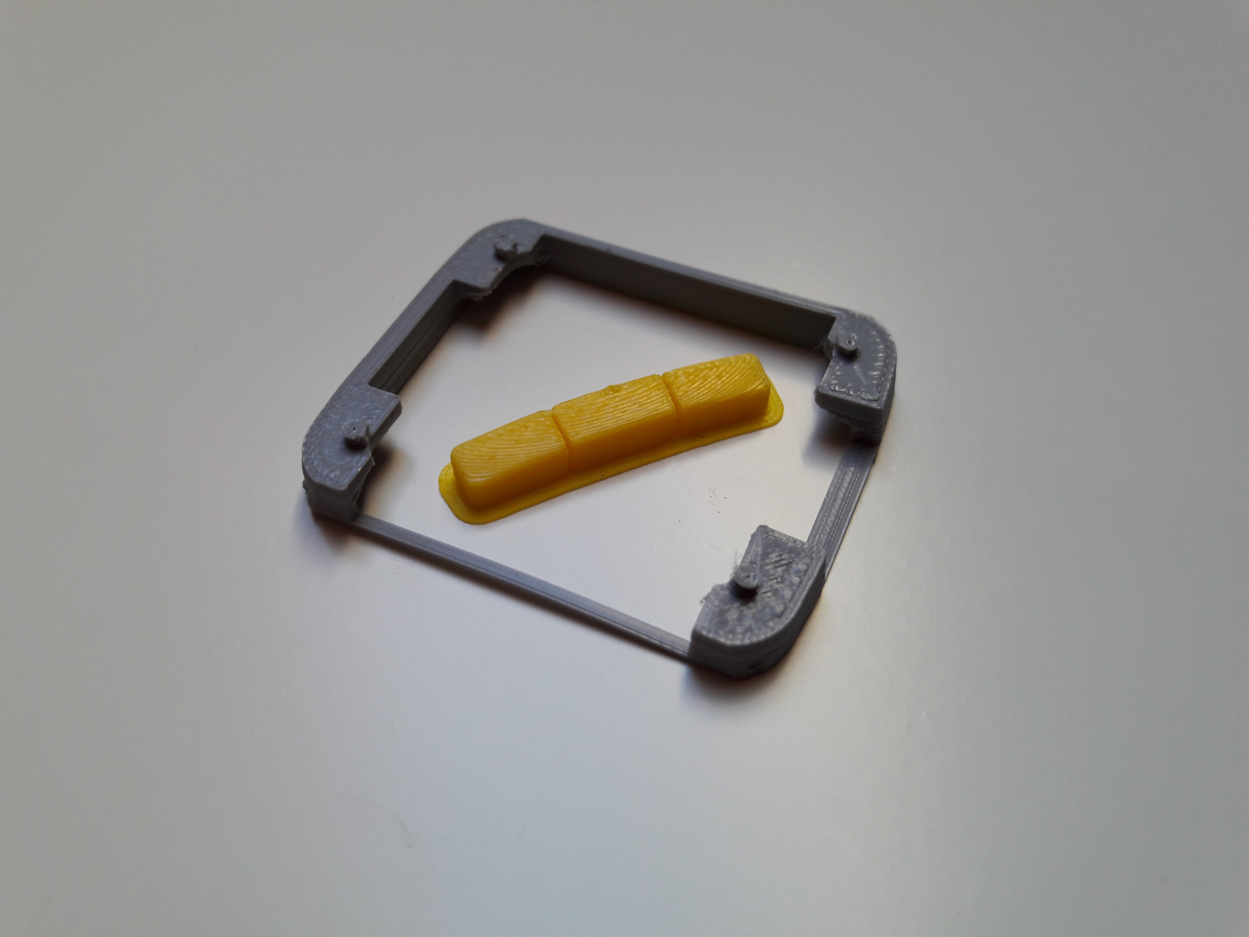
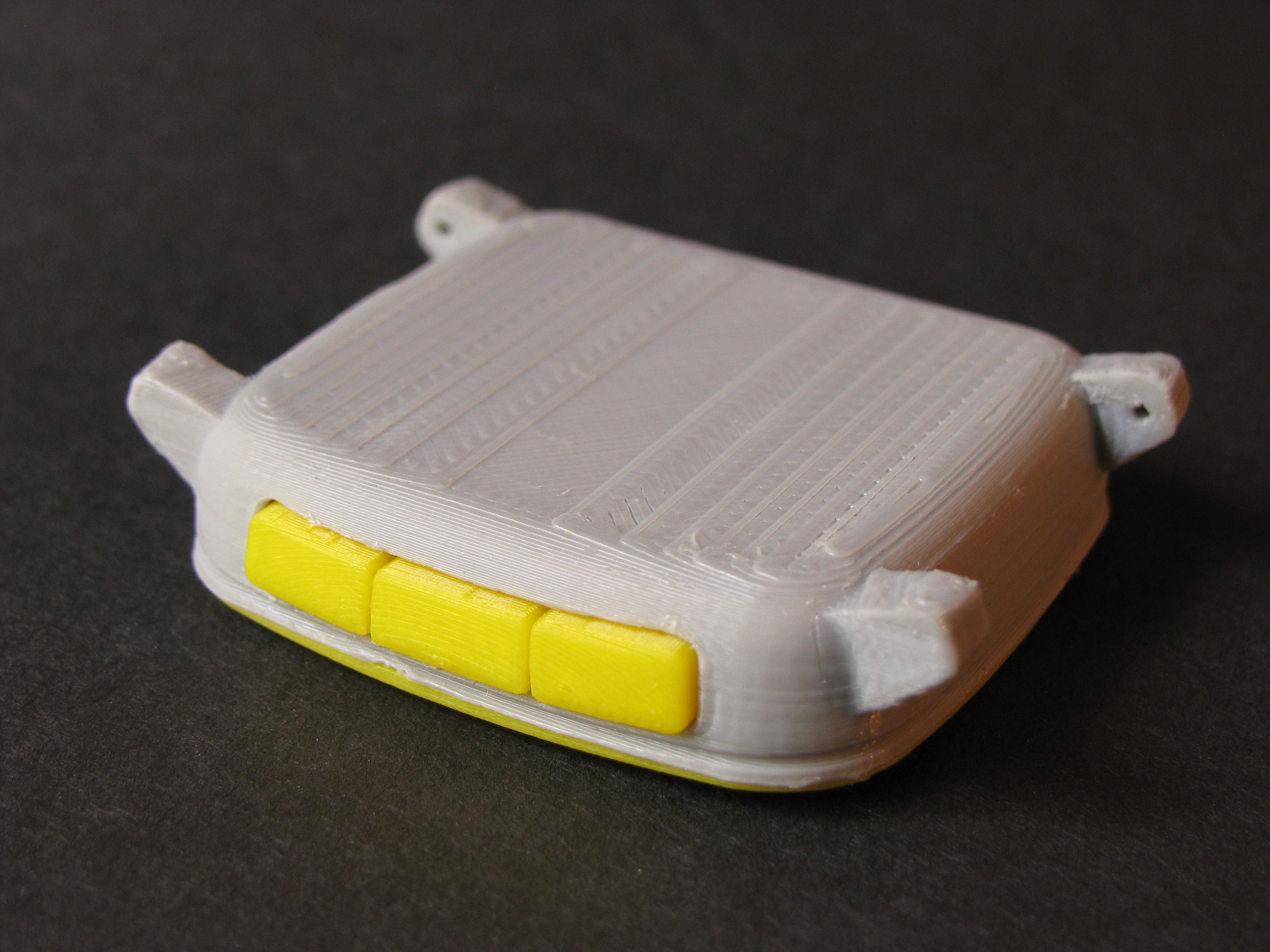
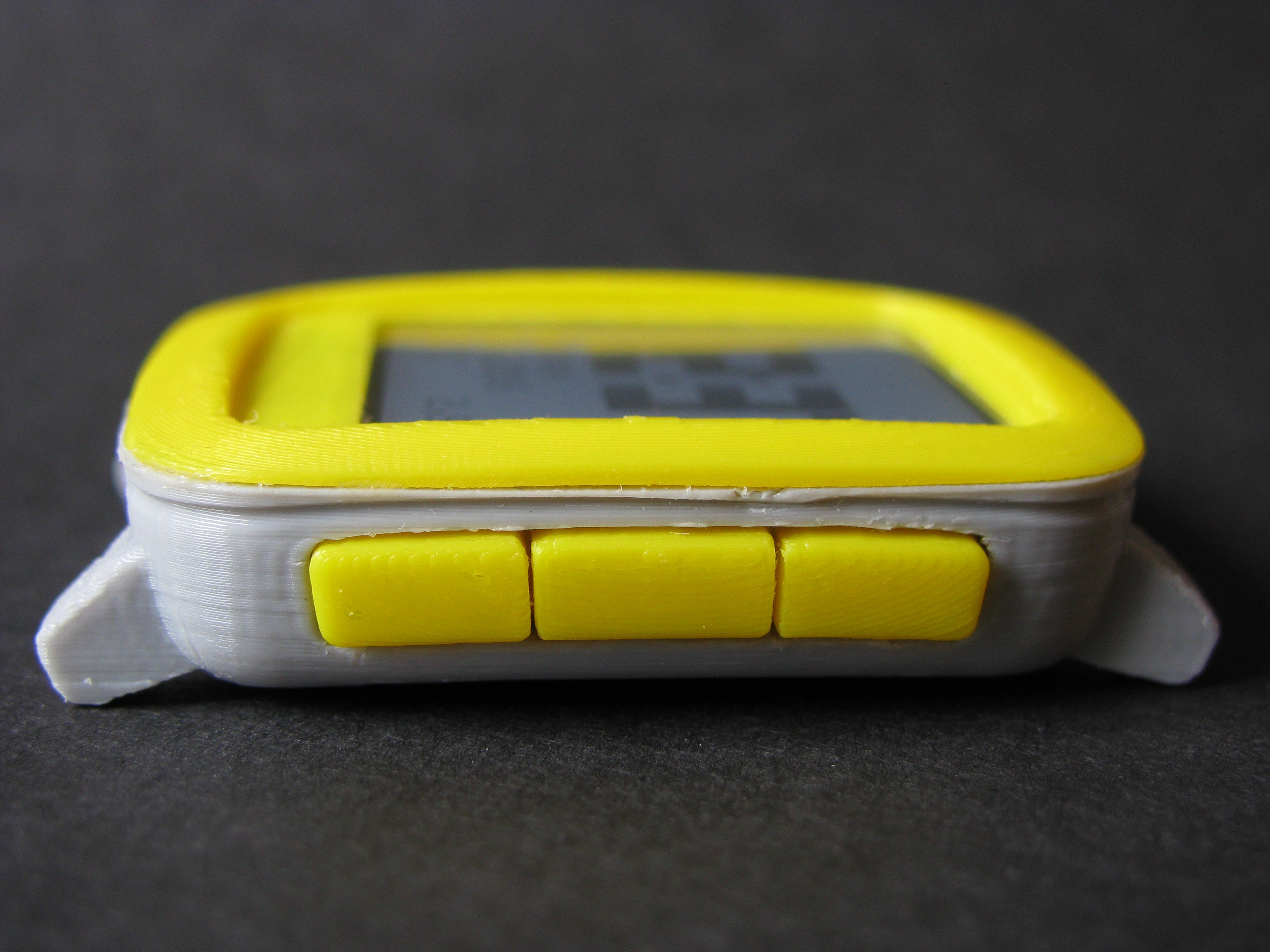
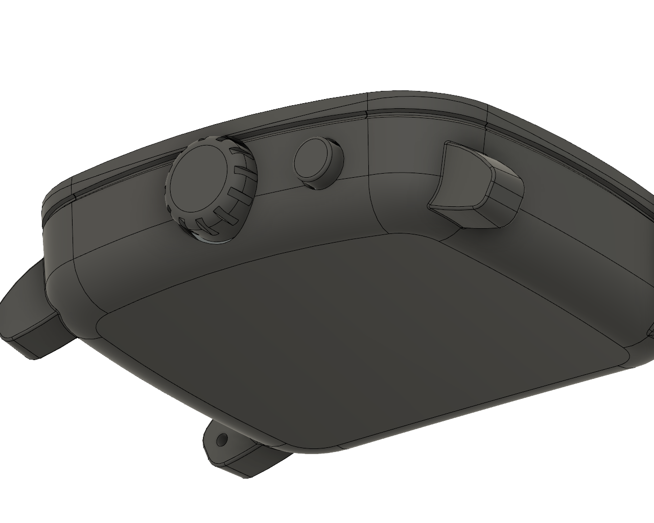
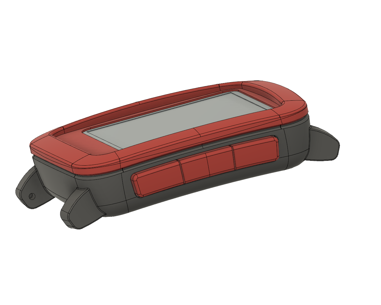
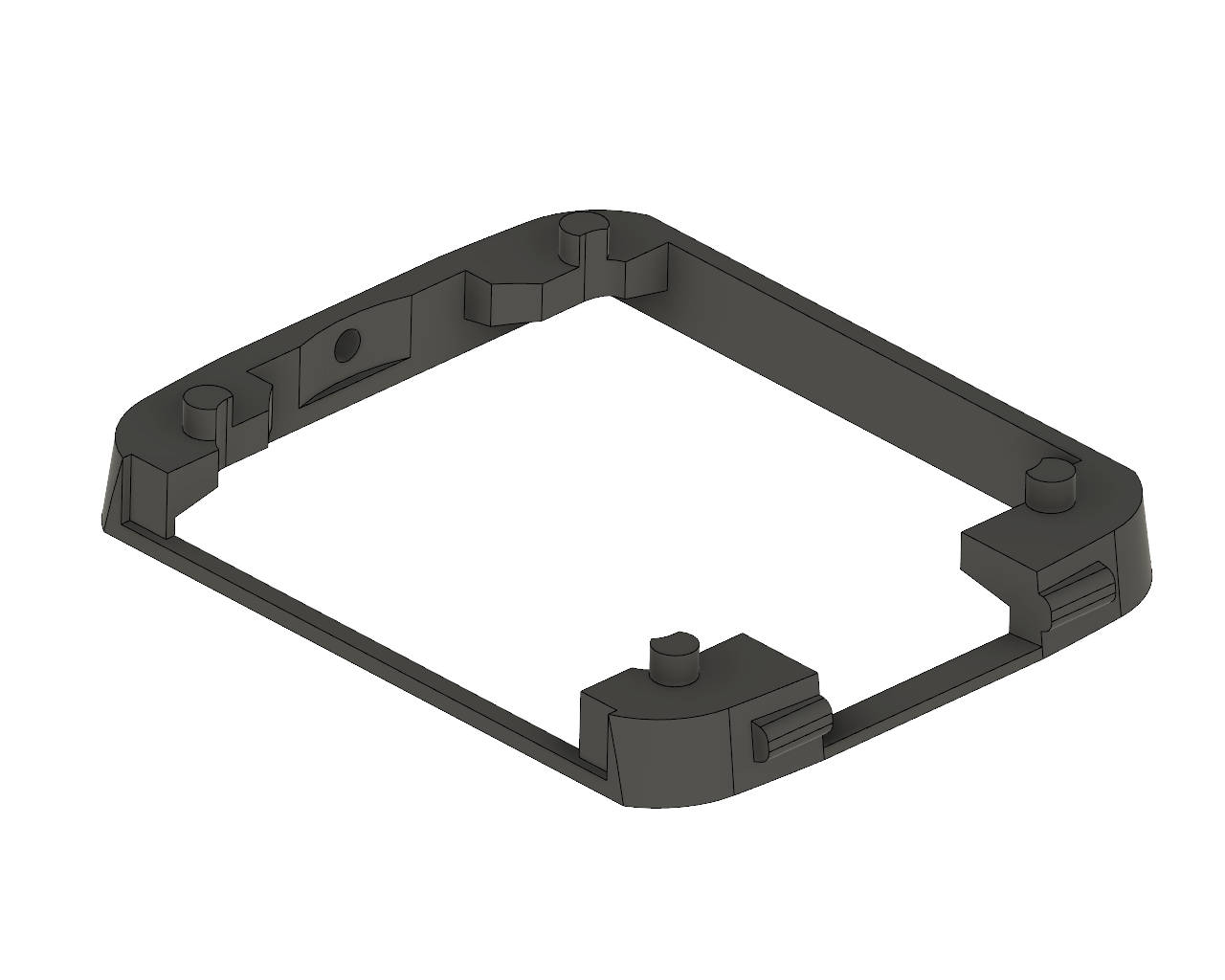
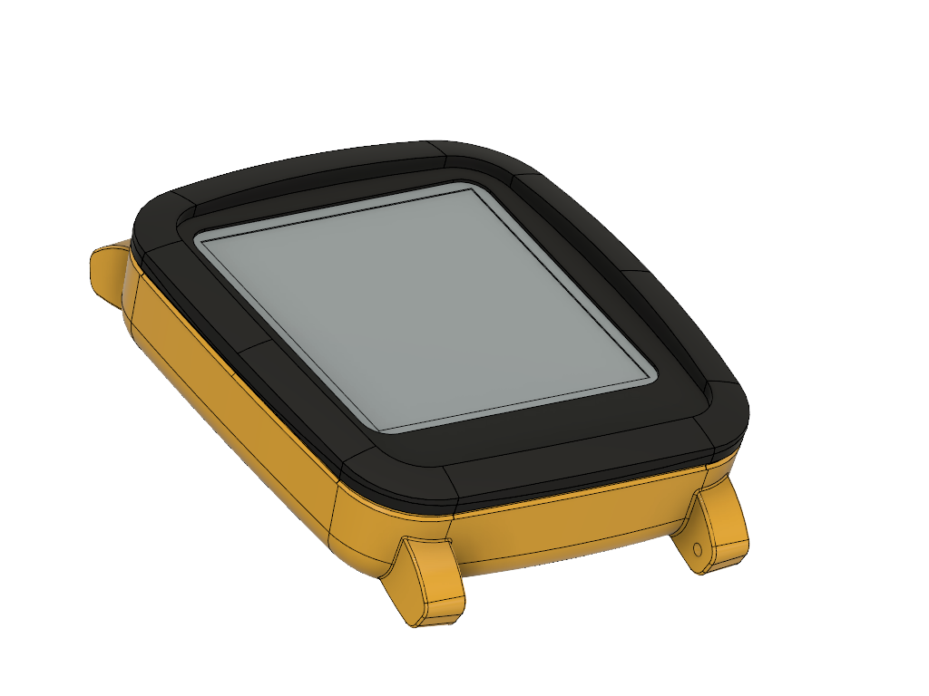
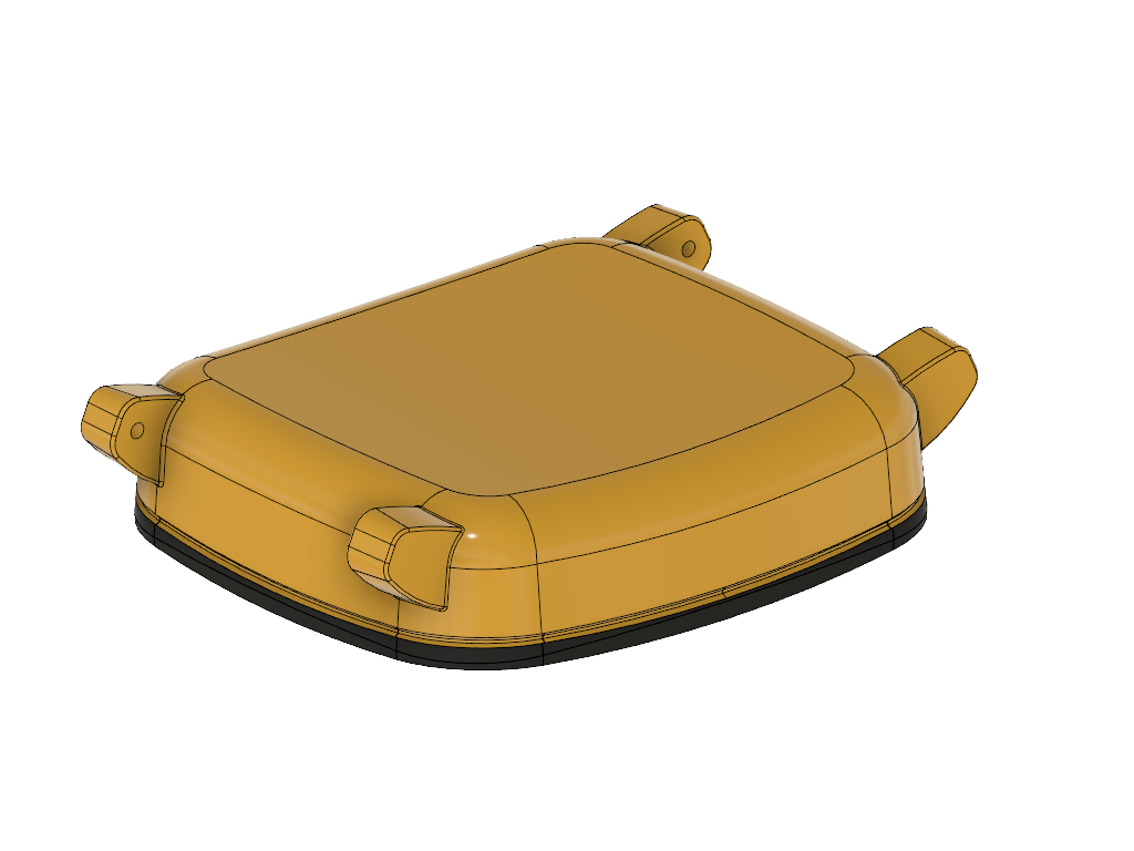
  • User Interface controllable with three side buttons. Buttons are 3D-printed and activate switches on the PCB
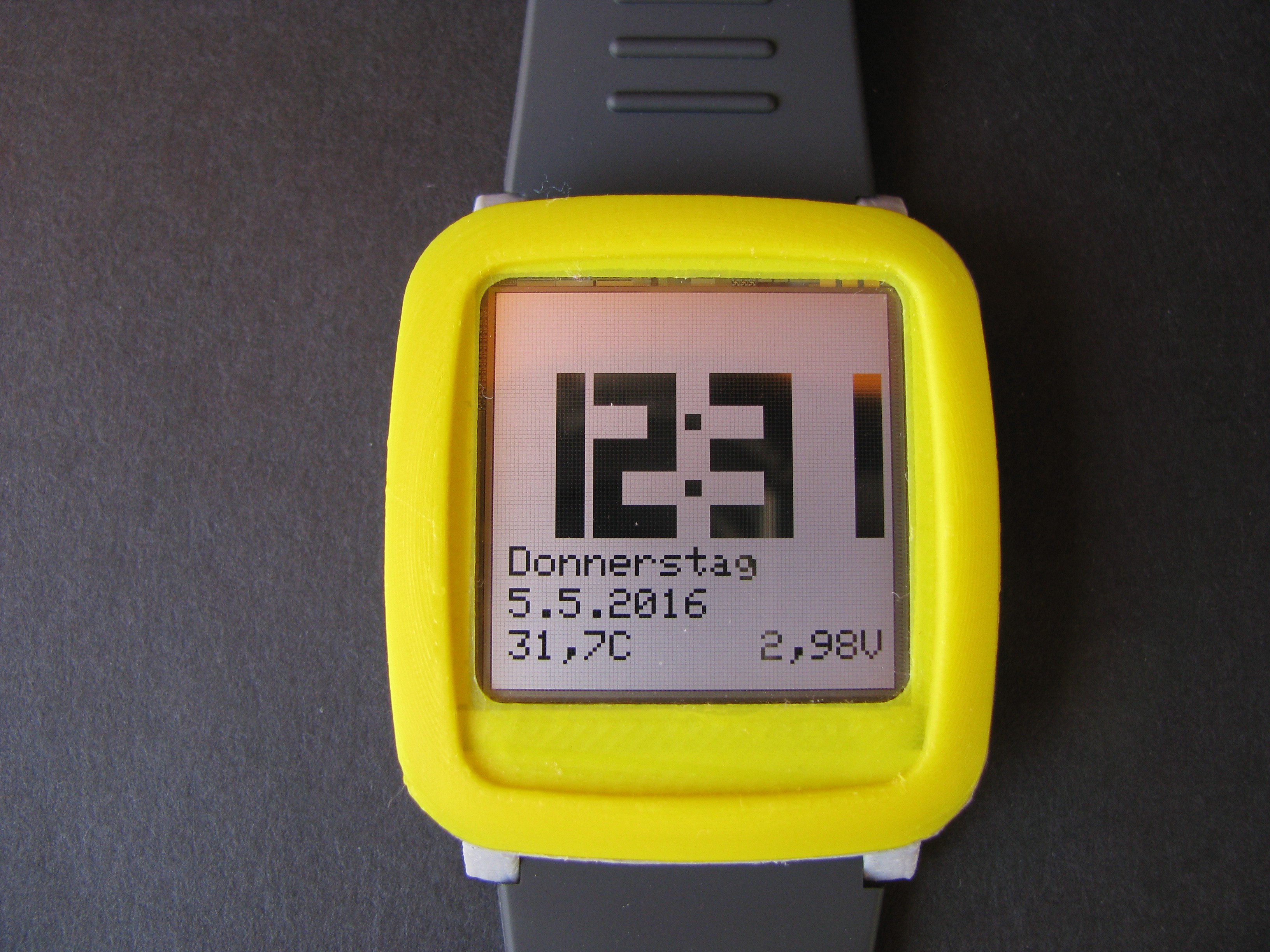
  • Tells time, date, temperature and battery voltage on the main screen. No additional temperature sensor is needed, because the DS3231 already has one integrated for temperature compensation.
  • Stopwatch
  • Flappy Bird clone ("That would have been cool in 2013")
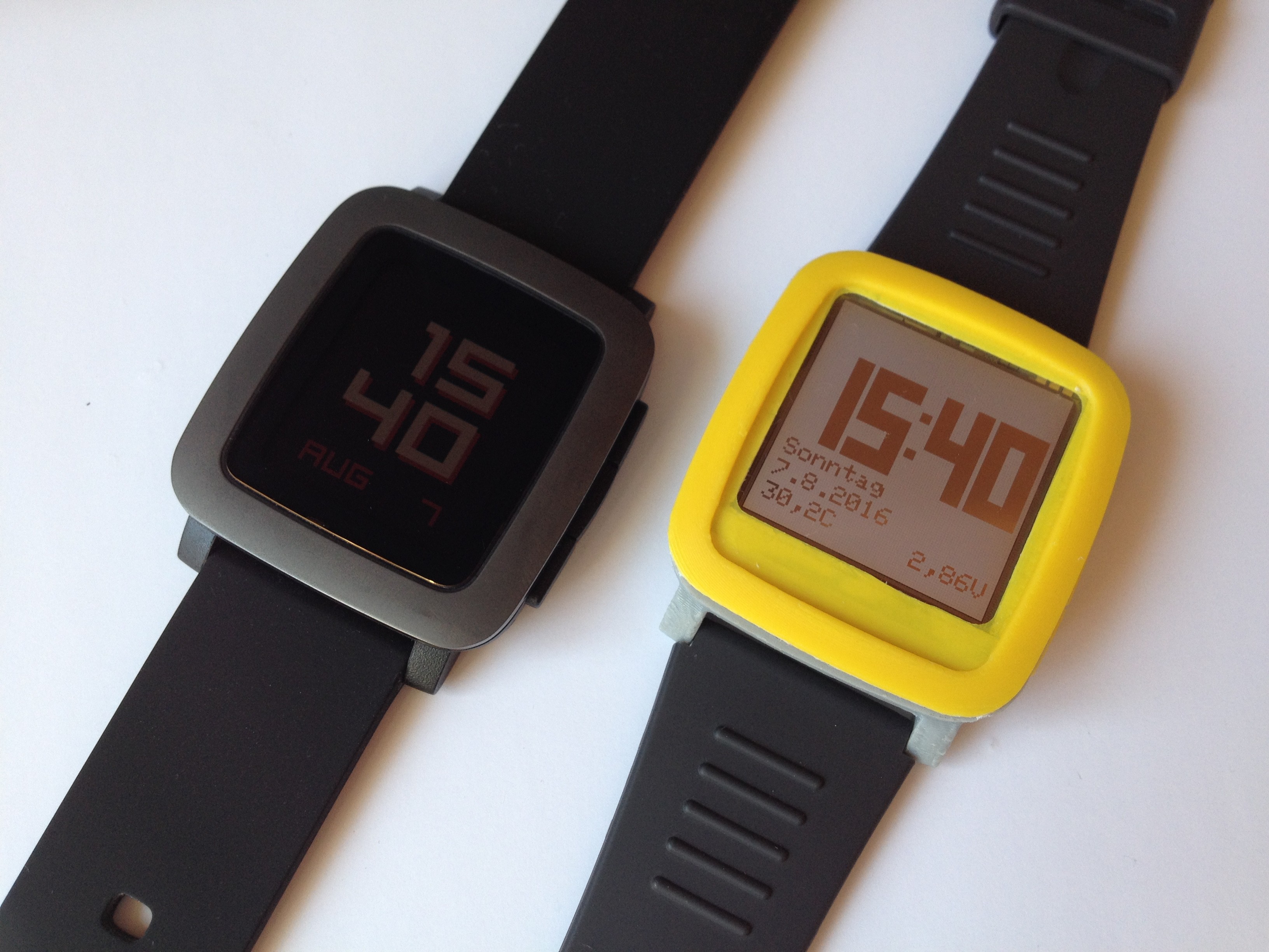
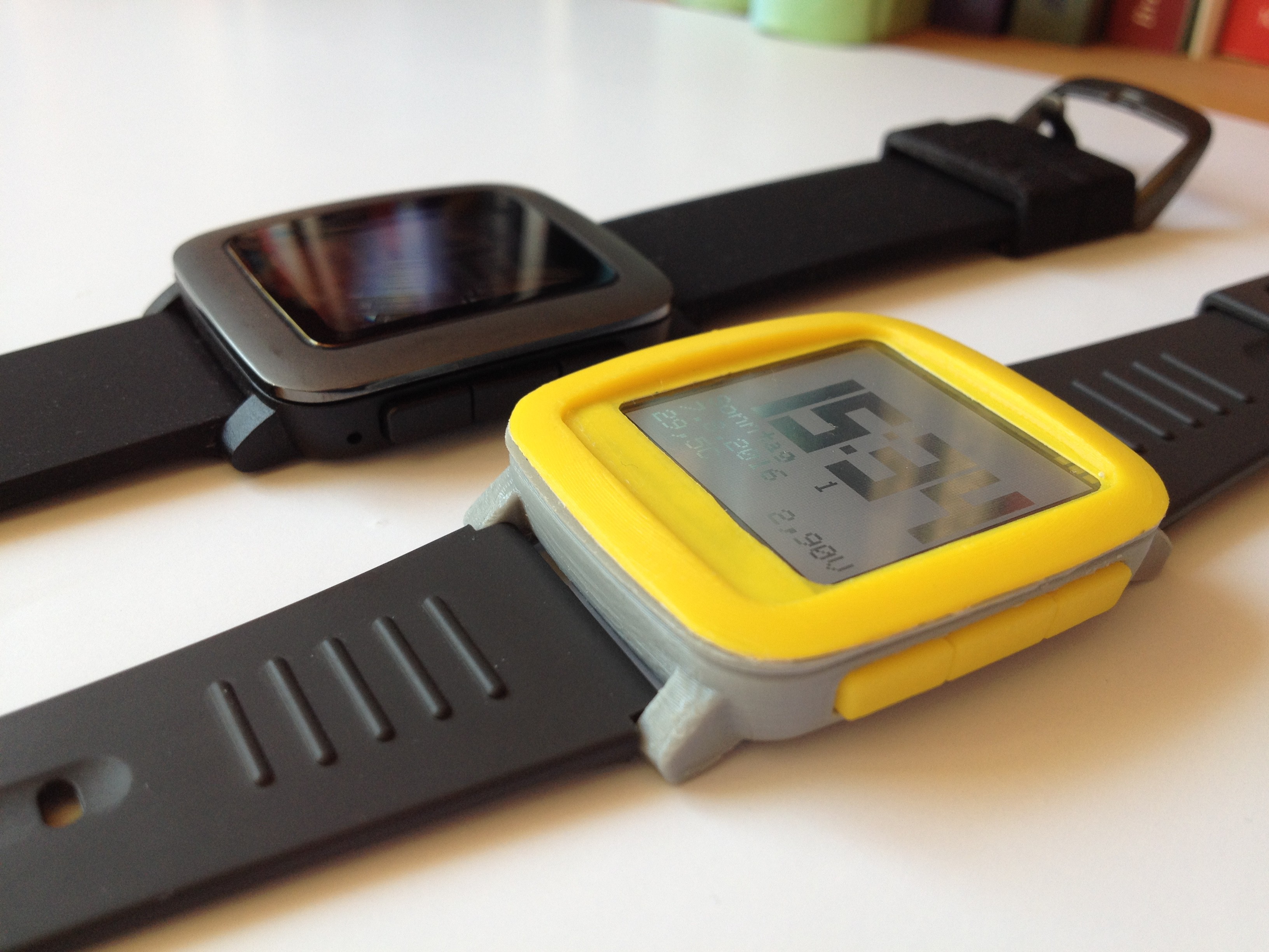
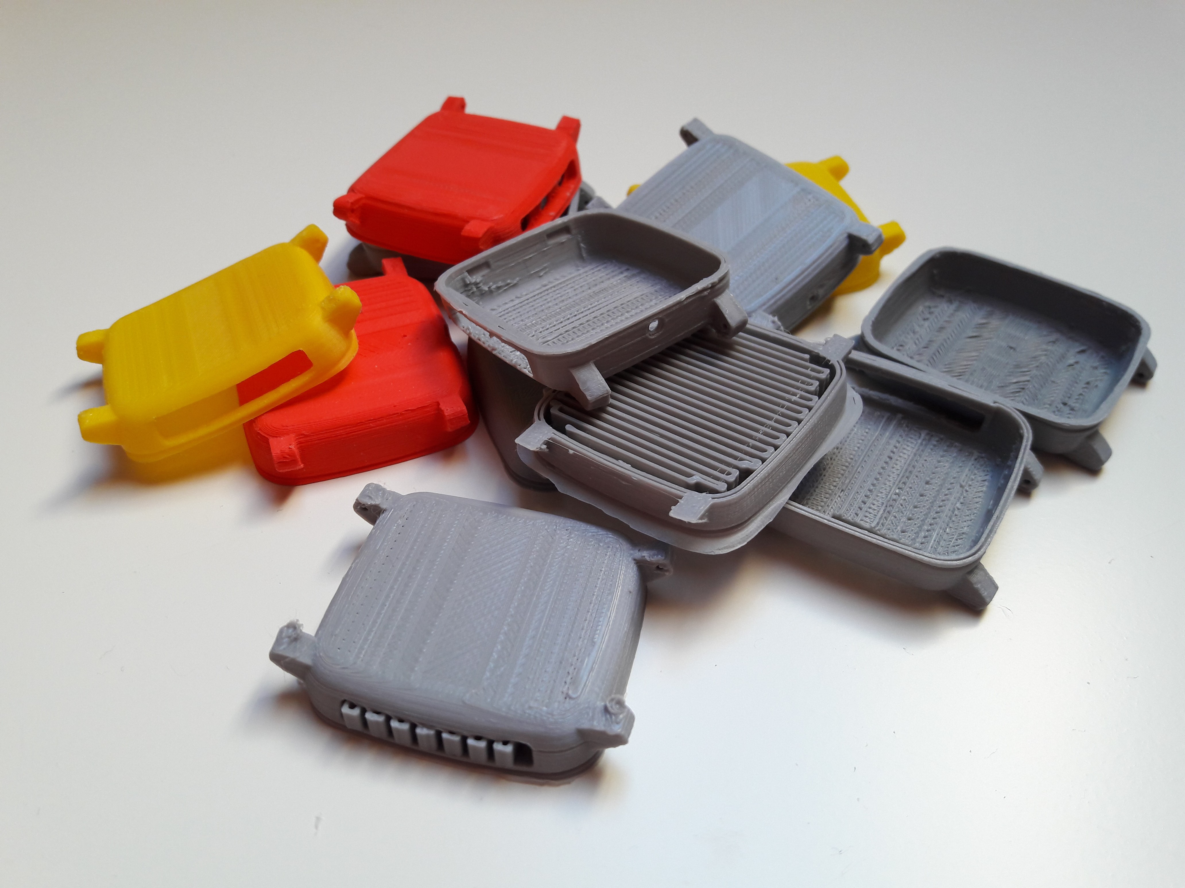
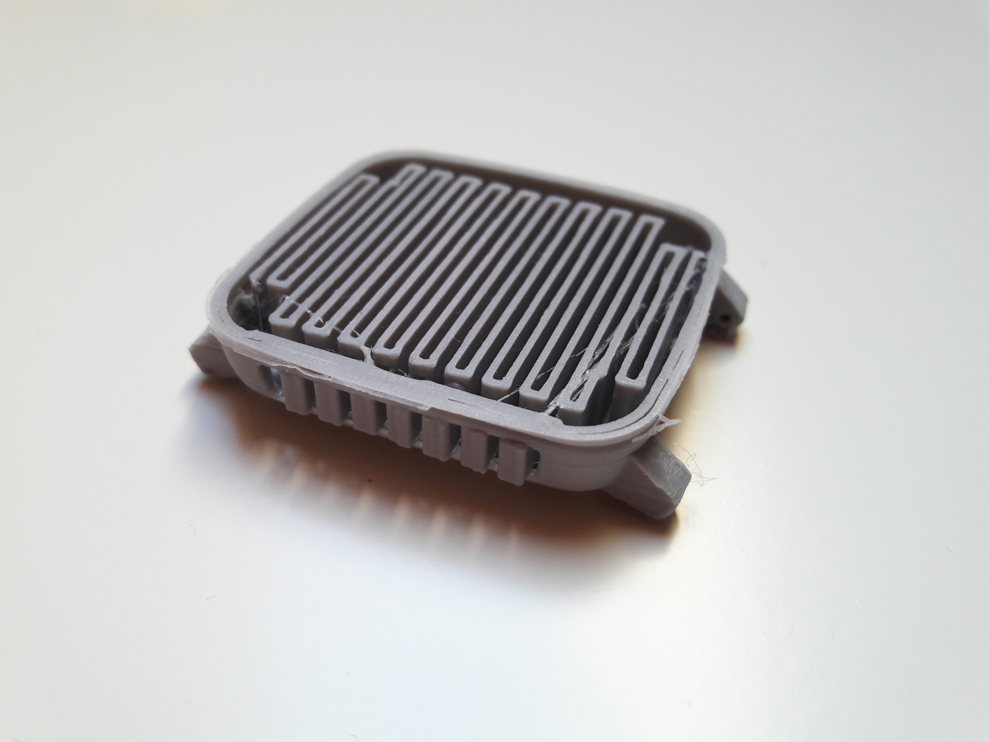
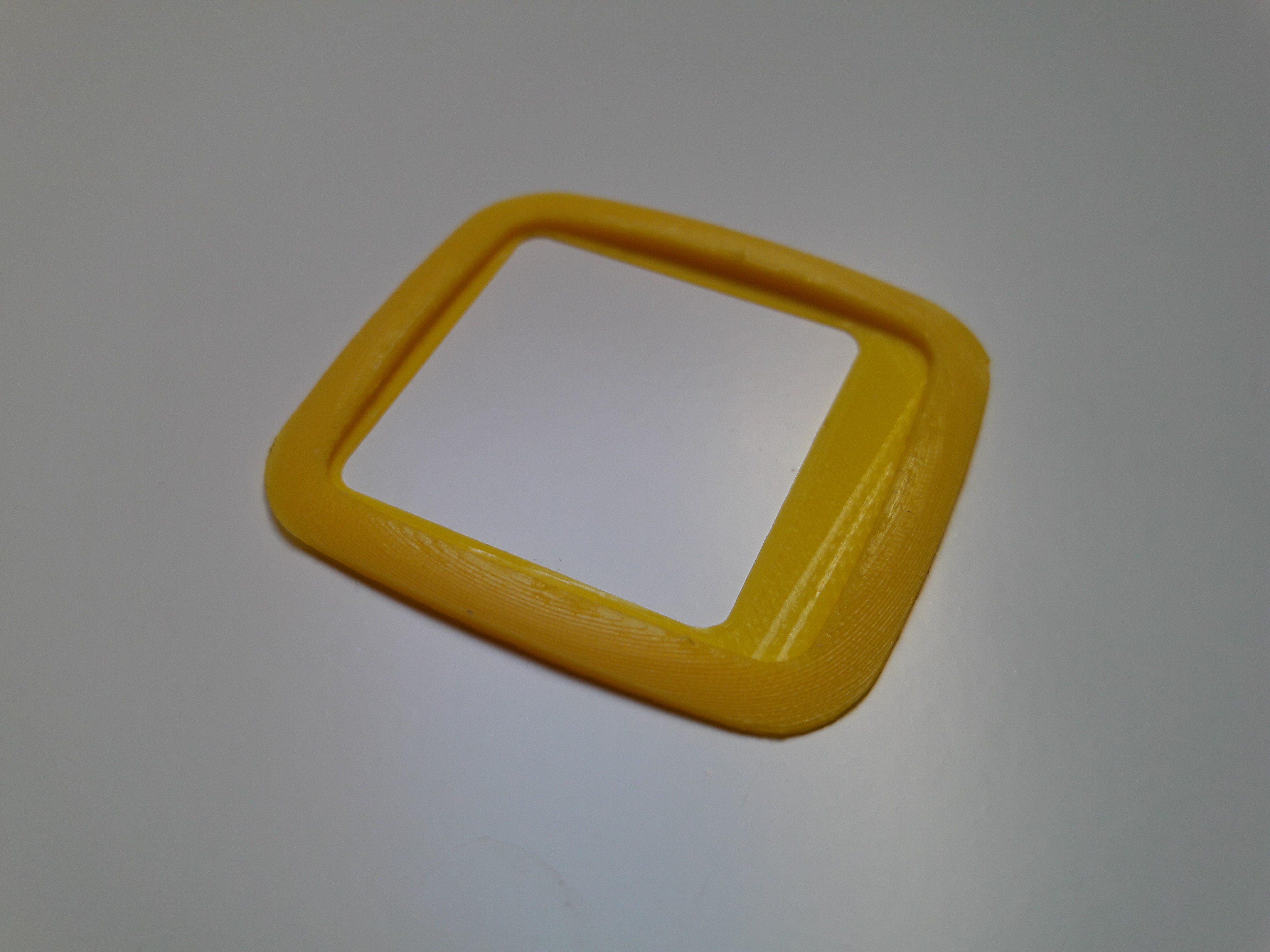
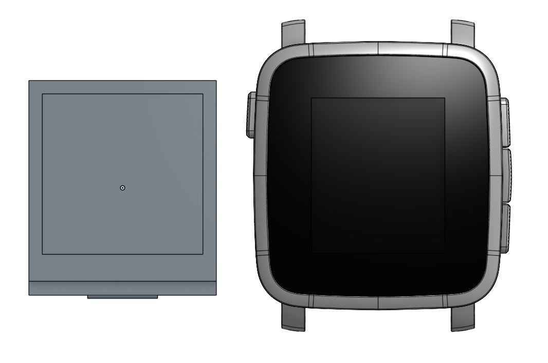
  • The case consists of four 3D-printed parts. It has a thickness of only 10.8mm, which is thinner than the Apple Watch. Unfortunately it lacks screen protection.
  • Fits any 22mm Watchband

watch.f3z

Fusion360 Design Files

f3z - 18.29 MB - 09/28/2020 at 19:40

Download

Chronio REV3 Schematic.PNG

PCB available on OSH Park: https://oshpark.com/shared_projects/VMKV49uK

Portable Network Graphics (PNG) - 56.30 kB - 09/18/2016 at 13:54

Preview
Download

STL files.zip

Also available on Thingiverse: http://www.thingiverse.com/thing:1762506

x-zip-compressed - 775.99 kB - 09/18/2016 at 14:00

Download

  • Source Code Released + 6 Months Run-Time Achieved

    Max.K02/01/2017 at 12:00 0 comments

    Starting with the battery life, the watch has now been running since August 7. In a previous project log I showed that the calculated run-time would be up to 6 months, which has been achieved now. The voltage has dropped to about 2.8 V, so it might last for a couple more weeks.

    Additionally the source code is now online on GitHub: https://github.com/CoretechR/Chronio

    As the pcb and 3d printing files have already been released, there is nothing more you need if you want to build your own copy of the watch.

  • Testing Battery Life

    Max.K10/19/2016 at 16:49 0 comments

    After assembling the third revision of the watch, I decided to test its battery life. Chronio is now running off of a CR2025 coin cell since August 7. During this time the display and RTC are on and the Atmega wakes up once per minute.

    The calculated battery life is about 6 months, although that is not an accurate number. The varying current consumption caused by the 1 Hz generator makes it difficult to predict the actual battery life. Because of this there is no way around a real-time test to see how long the watch will last.

    Next to the time and date, Chronio displays the battery voltage. For the past few weeks the voltage was between 2.84 and 2.86 V depending on the temperature of the room. Unfortunately Lithium-Ion batteries have a discharge curve that is anything but linear. Here is a graph from a very similar project with a CR2016:

    The voltage stayed at 2.85 V for the first half of the test before it slowly began to drop. Based on this, it is very likely that the watch is still within the first half as well.

    However, the test has already proven, that the watch will work for more than 2.5 months, which is more than twice of what I originally had hoped for. Also, this is the longest run of an Arduino I ever did. I had already expected some errors because of overflows. But Chronio even handled the overflow of millis() after 49 days without a problem.

    I would assume that the battery will probably last until the end of the year, which would be a nice 4 months of runtime.

  • Pebble Time Comparison

    Max.K09/15/2016 at 14:21 0 comments

    Originally I wanted to build my own watch rather than getting a regular smartwatch. But as the price of the Pebble Time dropped over the past months, I couldn't resist buying one. Even if it was only to see how it compares to my watch.

    The Pebble Time was without a doubt the main inspiration for this project. The case is almost the exact width and length, only the thickness was not doable. Chronio's screen has a much lower pixel density and is only black/white. Then again it is 24% larger than the Pebble's, reducing the bezel size noticeably. In terms of processing power and features, the watches are not really comparable. The ATmega328 is no match against a Cortex M4, which can handle color graphics and animations but has a high power consumption. This is where Chronio has its biggest advantage: battery life. It can display the time for several months until the battery needs to be replaced. The current prototype has been running for 6 weeks now. However the Pebble Time lasts a week on a charge, which is still a lot compared to Android Wear or Apple devices. Disabling Bluetooth extends its battery life to about a month.

    ChronioPebble Time
    Dimensions40.3 × 37 × 10.8 mm40.5 × 37.5 × 9.5 mm
    Screen96 × 96 px white/reflective144 × 168 px 64-color
    Screen size24.2 × 24.2 mm20.1 × 23.44 mm
    Battery 3 V 165 mAh
    CR2025 coin cell
    3.7 V 130 mAh
    Li-Ion (rechargeable)
    Battery life~ 6 months~ 1 month (airplane mode)
    Processor16 MHz ATmega328P100 MHz ARM Cortex-M4
    Additional featuresTemperature sensorBluetooth, Microphone,
    Compass, Accelerometer,
    Backlight, Vibration motor,
    Apps/Watchfaces

    In conclusion, the project was a great way to learn about low power electronics. It may not be the best watch to wear on a daily basis, but building it was a lot of fun and I would definitely consider the project a success as I already exceeded the month of planned battery life.

  • The Adventure of Generating a 1 Hz Signal

    Max.K09/12/2016 at 14:48 17 comments

    As explained in an earlier project log, the watch was at a point, where it only needed 2 μA in standby mode. Then screen burn-in started showing up and the watch stopped after only a couple of days.

    After checking the display's datasheet and application note (http://www.sharpmemorylcd.com/resources/programming_memory_lcd_app_note.pdf) once again, I found a detail I had missed completely: Although the display does not need constant updating, there is a VCOM inversion signal that needs to be generated. "VCOM is an alternating signal that prevents a DC bias from being built up within the panel", meaning that burn-in will occur if the signal is not supplied. The signal can either be generated by software(which the Adafruit library already does) or by a dedicated input pin (EXTCOM). Also a short pulse is not enough, the display needs a 50% duty cycle square wave with a frequency of at least 1 Hz. This was a major problem, because the low power consumption of the watch relied on the Atmega being in standby most of the time. Waking it up every second to toggle a pin would decrease battery life dramatically, which had been the main advantage of this project. Generating the signal by software would not work without the Atmega waking up, so it had to be supplied over the EXTCOM pin. A 1 Hz square wave can't be too hard to generate, or can it?

    As it turns out, it can be if you are limited to a few μAs of current and a tiny watch to fit in. The easiest approach would be a 555 timer with some passive components. Although there are hundreds of variations of this chip, I could not find a single one with less than 50 μA of operating current. In the Arduino forum, a schmitt trigger oscillator was suggested to me (http://forum.arduino.cc/index.php?topic=400656.0). The Schmitt trigger itself and the oscillator you can build out of it are explained in detail on Talking Electronics: http://www.talkingelectronics.com/pay/BEC-2/Page49.html. It is basically an inverter with hysteresis than you can use to make an oscillator. At first the idea looked very promising. I got a square wave out of a Schmitt trigger inverter (74HC1G14GW), a 10 MOhm resistor and a 0.1 μF capacitor.

    But the problem was again the power consumption. The current draw was varying but at hundreds of μAs. Although the Schmitt trigger usually only draws 10 μA, according to the datasheet there is a delta-current of up to 500 μA, which is needed if the input voltage is in between 0 and VCC. This means, if you are at 3.3 V, the inverter will output 0 V and only draw 10 μA. But if you are at 1.3 V for example, the operating current will be much higher.

    Another solution was using a real time clock to generate the signal. Most RTCs have an output pin for a 1 Hz square wave. The DS3231 has such a pin as well, but this feature cannot be used while also having the 1 minute alarm running. There was no way around a second RTC. I didn't want to use another DS3231, because they are relatively expensive at about 8 €. I found the MCP79410 from Microchip, which had a low operating current and the features I needed for only 1 €. Then I made a second PCB revision including the new RTC and fixing some errors from the first version.


    The second revision also includes the DS3231 in a smaller package and moves it to the top side, making room for SMD buttons. Also I switched to the improved programming interface. The traces were still all over the place.

    As I wanted to get the project done quickly, I made a lot of errors in the process. One was that I forgot to include an oscillator for the MCP79410. I fixed that by soldering an SMD oscillator directly to the pins. Luckily no additional capacitors were needed. The 32.768 kHz output of the DS3231 can't be used instead of the oscillator because that pin is open drain. With this high frequency you would need a small pullup resistor, which draws too much power.

    I got the MCP79410 to work at only 2 μ...

    Read more »

  • 3D Printing

    Max.K09/11/2016 at 14:48 0 comments

    After designing the watch in Fusion360, I had to print the parts with a 3D printer, in my case the bq Prusa i3 Hephestos. As a material I am using PLA, mainly because it doesn't smell as bad as ABS. The main challenge was getting the case printed with a smooth surface. As there is only one main part for it, supports are crucial. I started with Slic3r, but soon switched to Simplify3D because of its adjustable supports. Still, it took a lot of failed attempts to get all the settings right.

    This is what the parts looks like after printing:

    After carefully removing the supports, I used an Exacto knife to clean up the part.

    For the buttons and cover I lowered the layer thickness to 50 um. This is because these parts are really small and only slightly curved. It's ok if the they are recognizable as 3D prints but they should not look too edgy.

    The last part is the "spine". There are no high demands to it, as it will not be visible from looking at the watch.

    To explain how the individual parts are assembled, I played around in Fusion360 and created this GIF:Basically, all components apart from the buttons and case are supposed to be glued together. Then this assembly is placed in the case with the buttons, where it will snap in on one side. A small screw will then secure it from falling out of the case. I ended up using double sided tape for the whole process and tiny drops of superglue to secure the display. Attaching an 22mm Casio watchband was the last and easiest step.

    The end result turned out really well in my opinion. It is obviously not nearly as usable and durable as a industrially manufactured Pebble watch. But it can definitely be worn as a watch and the battery life almost justifies that you have to open the case to replace the coin cell every few months.

    I am releasing the stl.-files on Thingiverse, in case someone wants to build this project:

    http://www.thingiverse.com/thing:1762506

  • Improving Battery Life

    Max.K09/06/2016 at 21:10 1 comment

    The overall power consumption depends on how much current the device will draw in active or standby mode and how much time it will send in these modes. I measured that with my code, the Atmega takes about 100 ms from triggering the interrupt to going into sleep mode again. This process happens once per minute to update the display. This means that only 1/600 of the time is spent in active mode, where the watch draws around 5-7 mA. So my main focus was the current draw in standby.

    Although the first version of the PCB was already functional, it was drawing around 450 μA in standby. The original goal of this project was to get below 100 μA, which would equal 1-2 months of battery life with the CR2025 (160mAh). For calculating this, Oregon Embedded has a very nice online tool: http://oregonembedded.com/batterycalc.htm.

    Finding out where a device is wasting power can be tricky. Luckily the first PCB only had three active components: The Atmega, the RTC and the display. After unplugging the display and soldering off the RTC, the standby current was still at a nearly 400 μA. As the Atmega has an advertised sleep current of 100 nA, something was off. The first thing I noticed was, that after leaving out the voltage monitoring part of the code, the sleep current got down to 280 μA (with RTC and display reconnected). It turns out, that when measuring the battery voltage, the ADC (analog/digital converter) gets activated and stays on even in standby. The current consumption by this module significant. Turning it off completely in the ADCSRA register, reduced the sleep current to only 130 μA. One way to solve this problem without loosing the functionality is turning the ADC off before entering sleep mode. But I instead switched to a library that does this automatically, lowPower by Rocketscream: https://github.com/rocketscream/Low-Power. It also has an option to turn off BOD (brown-out-detection), which means that the Atmega might do weird stuff if the battery voltage gets critically low. By doing that the sleep current was reduced to 110 μA.

    I already would have considered 110 μA a success at the time, but there was one more thing I was able to do. I figured out, that the Atmega was basically running at its advertised 100 nA, as I was not able to measure the current with my multimeter anymore. The DS3231 was the one draining over 100 μA by itself. After checking the datasheet, I found out, that by using only the dedicated battery input pin (VBAT) to power the RTC, the power consumption can be greatly reduced.

    To verify this, I bent the VCC and VBAT pins of the device up to disconnect them from the traces on the PCB. I then connected the VBAT pin to the VCC line and left the VCC pin floating. The improvement of doing this was not just a few μAs. The entire sleep current of the watch was now at 2 μA. This would equal over a year of battery life.

    I now had a fully functional prototype with an incredibly low power consumption. Unfortunately it didn't stay that way for long. While running a first test, the watch stopped after just about 5 days. Also the screen was showing more and more burn-in, that would disappear after removing the battery for a few minutes. Solving this problem turned out to be a lot of work, so I will dedicate a separate project log to it.

  • Programming

    Max.K09/04/2016 at 16:56 0 comments

    Interface

    The first step is burning the bootloader onto the Atmega328. I included some testpoints for the ISP pins, so it was just a matter of following the instructions on this site: https://www.arduino.cc/en/Tutorial/ArduinoToBreadboard

    After this, the Atmega can be programmed using the serial interface. Including power, 5 pins are needed: TX, RX, Reset, Ground and VCC. The first version of my PCB simply had the footprint for a pin header on it, so I just soldered wires to it. For the later versions I wanted a proper adapter that can be connected to the PCB without soldering.

    The interface on the PCB consists of 5 smd pads for the actual signals and two vias for centering the adapter. This design is based on the Protoprog: http://protofusion.org/wordpress/2013/05/open-hardware-pogo-pin-programmer/. The adapter uses a 3D-printed part with pogo-pins. On the other end it has a pin header that can be plugged into a breadboard. Because I had trouble with the printed part, I ordered a tiny adapter board from OSH park. On the breadboard I used a simple level converter (CD74HC4050E), so the 3.3V components are not damaged by the 5V Arduino Uno that I am using to program the board.


    Arduino Code

    Clocked at 16 MHz, the ATmega328 consumes more than 3mA. This will drain a button cell in a matter of hours. Luckily there is a 100nA sleep mode. In this mode the Atmega is basically turned off and can only be activated again with external interrupts. One of the two available interrupts is connected to a dedicated pin on the DS3231 real time clock. The clock is programmed to generate a pulse once per minute. This makes it possible to only turn on the uC for a short period of time to update the time and display. The display itself is controlled over the SPI interface. I am using the adafruit gfx library, which has very nice functions for basic geometry and text: https://github.com/adafruit/Adafruit_SHARP_Memory_Display

    To wake up the watch intentionally, the middle button is connected to the second hardware interrupt. The debouncing is handled by a library as well (https://github.com/JChristensen/Button).

    The user interface is organized in pages. The main screen is page 0, the menu page 1 and so on. The currently implemented features are a stopwatch, a menu for setting the time, a debug menu and a flappy-bird game.

    The always-on watchface displays the time in big digits. Instead of using a font from the adafruit library, I wanted to create a custom font. It combines rectangles to create the digits and is easily readable even from a distance. Besides time and date the watchface show the temperature. This is done by reading the internal temperature sensor in the DS3231. Additionally ther battery voltage is displayed. For this, I am using the internal voltage reference of the Atmega. Most of the code is copied from here: http://provideyourown.com/2012/secret-arduino-voltmeter-measure-battery-voltage/. On a lithium battery you get a very non-linear discharge curve. It should be useful as a low-battery-warning though.

  • User Interaction

    Max.K09/01/2016 at 13:38 0 comments

    To navigate through a menu, the watch needs some kind of input method. My original idea was to copy the apple watch with its digital crown (which is a fancy word for an encoder). I even found a fitting encoder from ALPS(http://de.farnell.com/alps/ec05e1220202/encoder-horiz-5mm-12det-12ppr/dp/2064967). I then modeled and printed a case and glued in the encoder. While it may have worked, properly fitting the component and a 3D-printed knob inside the case would have been impossibly complicated.

    I then switched to a solution using buttons. As I took over most of the design of the Pebble Time anyway, it was a logical step to also put the buttons in the same place. To save space, my design does not use a fourth button on the left side. Even 3D-printers get along with only three buttons.

    What I wanted to avoid, was having cheap through-hole-buttons stick out of the case. The buttons should be separate printed parts. These would then activate tactile switches on the pcb. The idea sounded simple in my head at the time, but getting it to work was a real challenge.

    The first step was modeling the buttons. I wanted to get close to the Pebble Time, while still getting parts that can be printed without supports. This is achieved by having a curved surface on the outside and a flat surface where it is connected to the watch. Also, the whole thing should take up as little space as possible. I then made different versions, varying in how the printed buttons would be split from the case and they would be connected to the switches.

    Version 1 already used a single part for all three buttons, connecting them with only a single layer of plastic to remain flexible. The case has a cutout for the buttons and three holes to the tactile switches. These were then glued to the inside. In a last step the printed buttons would be carefully glued to the protruding parts of the switches.

    The problem with this was that the printed buttons were only secured by three drops of glue. Also the tactile switches would have had to be permanently glued inside the case, making it difficult to connect them to the removable PCB.

    Version 2, which is used in the final build, solves these problems by mounting the buttons from the inside of the watch. A small seam prevents them from falling out of the case. The PCB with its switches secures the printed buttons from the opposite side.

    This version is working very well at the moment. The only problem is the weak actuation force of the SMD switches I am using. I solved this by gluing top-actuated switches to the edge of the PCB and connecting them with short wires. It's not a perfect solution for mass-production but pressing the buttons has a nice feel to it. It actually seems more sturdy than the mushy buttons on my real Pebble Time. I guess this is because they needed water-protection and used very thin switch domes.

  • PCB - Revision I

    Max.K08/26/2016 at 14:34 2 comments

    This was my first custom PCB design, apart from a single sided milled PCB that I had to create for an assignment. Because most of the suppliers in Europe are really expensive, I chose OSH Park. They only charge 5$ per square inch, which is especially great for tiny projects like this. I have no idea how they can produce and ship boards around half the globe at that price.

    Is started with the schematics in Cadsoft Eagle. I basically just searched for components and then connected them. For the display I am using a ZIF connector. The Atmega needs an external 16MHz crystal to run at the normal clock rate of an Arduino. An additional led is for testing the board with the blink-sketch. For programming the Atmega I used the footprint of a 5-pin header. The cables could later be soldered on. As I had no Idea of how to include the buttons yet, I just put in some SMD pads.

    For the board layout, I did a quick mockup of the PCB in Fusion 360 and tried to find the right size, that would still fit inside the case. I ended up with a 34mm by 28mm rectangle with rounded corners. A small cutout helps the display's flex cable bend within the case. I placed four mounting holes in the corners for good measure. Holding the coin cell was another challenge. The standard SMD holders have a high profile. I put two pads next to the side of the coin cell and decided to make a custom mount.

    The routing took me a few hours. Mainly because I used relatively thick traces I ended up with dozens of vias. Also, the angles were all over the place. When the board arrived two weeks later, I had very low expectations. But there were no shorts or major design flaws.

    The next step was to populate the board. I ordered the components from Farnell. Very fast service and insane packaging even for low quantities like the two Atmegas.

    I soldered the board by hand. Thin solder and a flux pen are absolutely necessary for parts like the ZIF connector. For the coin cell mount I cut the metal strip of an old folder to the right length and soldered it to the board.

    After burning the bootloader, I used an old Arduino Uno and removed its chip to program the board. It basically worked on the first try without any modifications:

    After adding the screen and uploading the code, the watch was already working. To connect the PCB and display, I created a separate printable part.

    Although it is functional, the first board has it's problems. The current consumption in standby is still at 450 uA. Also the programming header is only a temporary solution.

  • Initial Design

    Max.K08/22/2016 at 16:34 0 comments

    I have been thinking about building my own watch for a while. The things that always kept me from starting the project were two main problems: Size and battery life. You can easily take a small LCD screen, plug it into an Arduino nano and call it a watch. But it will be difficult to make it look decent. Also, unless you have your display turned off most of the time, battery life will be limited to a few hours.

    The first step was finding components that solved these problems. The display usually consumes a lot of energy. A few commercial watches - like the original Pebble - solve this by using an e-paper-like display, that only needs energy for updating the screen. I came across the Sharp Memory LCD LS013B4DN04, which is a 96x96 pixel screen with basically no static power consumption. They cost about 20€. Adafruit even has a rather expensive breakout board (https://www.adafruit.com/product/1393) for them. I ended up buying the much cheaper Texas Instruments breakout board from Farnell (farnell.com/texas-instruments/430boost-sharp96/sharp-lcd-boosterpack-msp430-launchpad/dp/2429519).

    As I wanted to keep the project Arduino-compatible, I chose an Atmega328p as a microcontroller. It has a 100nA sleep mode, so I only had to find a way to wake it up when necessary. For this, the Atmega has two external programmable Interrupts. I ended up connecting one to a real time clock, which triggers once per minute. Now basically the only thing consuming power is the RTC.

    I chose a coin cell as a battery. A rechargeable Li-ion cell would require a charging circuit and a plug.

    For all of my projects in the past I used perfboards. To size everything down, I wanted to create my first ever custom PCB. But before that, I wanted to get a grip on how the watch should look. Therefor I took the components I already knew and arranged them in Onshape.

    I got a thickness of around 7mm including the lcd, pcb, Atmega and a cr2025 coin cell.

    Next, I wanted to see how big the watch would have to be and what shape it would fit in. I really like the Pebble time with its rounded corners. So this was a great design to start with. Pebble even has a Github page with their CAD-files (https://github.com/pebble/pebble-3d).

    The sharp display almost fits the pebble time, but because of the lower bezel it would not be centered. I decided I would stick with a slightly offset screen instead of making the whole watch larger.

    For designing the body of the watch I switched to Fusion 360. Mainly because a project of this size is not comfortable to work with online, especially with a slow internet connection.

    To make the body printable I split it in half. The bezel of the screen, which acts as a protector and design element is one part. The other is the main body, which is big enough to fit the electronics. What I ended up with is basically a copy of the Pebble Time, although I modeled it from the ground up. I tried to avoid 90° angles, to make for an organic feel. To hide the cut between the two parts, I included a curved seam.


View all 10 project logs

Enjoy this project?

Share

Discussions

SexyCyborg wrote 09/05/2016 at 08:10 point

Technical merits aside, it really is beautiful.

  Are you sure? yes | no

Jaakko Salo wrote 09/04/2016 at 10:30 point

Hi! Nice looking project there. How did you end up generating the 1 Hz signal for the Sharp display? In my current project I'm planning to use TPL5000 from Texas Instruments (http://www.ti.com/lit/ds/symlink/tpl5000.pdf). That should only draw some tens of nanoamps.

  Are you sure? yes | no

Max.K wrote 09/04/2016 at 11:55 point

I had the watch finished and running when I found out about the signal. It took me a few weeks and two PCB revisions to get it to work. Basically I am using a second RTC to generate the signal. But it's a little more complicated than that. There will be a dedicated project log about this issue. 

I never heard about the TPL5000. There doesn't seem to be a square wave output pin, so are you planning on waking the microcontroller every second? At least with an ATmega328, that is not very efficient. The only other solution that I know of is the TS3005. It can generate a 1Hz signal directly at only ~1uA. I didn't use it in this project because it is only available in a SMD package and hard to come by.

  Are you sure? yes | no

Jaakko Salo wrote 09/04/2016 at 14:14 point

I'm using ESP8266 myself, and it is too expensive to wake it up. I have been under impression that a pulse-like signal, that I could get from TPL5000, would be enough for VCOM, but I must recheck this.

  Are you sure? yes | no

Max.K wrote 09/04/2016 at 14:30 point

The datasheets says that a square wave with 50% duty cycle is needed. I tested it with something like 100ms/900ms and it still worked. But it is questionable if it will work for months reliably. With the TPL5000 you would get a ~30ms pulse every second. You would have to test it to be sure, but I'm not too optimistic.

  Are you sure? yes | no

Jaakko Salo wrote 09/04/2016 at 21:12 point

You're right, need 50% duty cycle. Need to work on this then :)

  Are you sure? yes | no

Dorijan wrote 09/07/2016 at 07:34 point

@Jaakko Salo If you turn wifi off and put it in the Low power mode before going to sleep, then ESP won't draw as much current as it would otherwise when you wake it.

  Are you sure? yes | no

Jaakko Salo wrote 09/07/2016 at 21:48 point

@Dorijan yeah, in fact I'm already doing that :) But I'm really looking to make my batteries last 1-2 years.

@Max.K regarding the pulse, I noticed I'm using the 2,7" model LS027B7DH01. That one doesn't seem to have the 50% duty cycle requirement as far as I can see. Maybe this is truly a difference between the models?

LS027B7DH01 datasheet mostly states "min 1us" regarding the pulse width as far as I can see.

  Are you sure? yes | no

Sean Hodgins wrote 09/02/2016 at 14:31 point

This is amazing. You should consider looking into a group called #wearenotwaiting or Project Nightscout. They are basically hackers dealing with diabetes. Right now they use the pebbles and different smart watches to monitor their blood glucose levels. If this could be made to connect with that system it would be great. 

I definitely want to build one of these. 

  Are you sure? yes | no

Max.K wrote 09/02/2016 at 18:46 point

Thanks! Acting as a display for a glucose monitor would be an interesting application. But it seems like most of the devices use wireless connections. I thought about including an esp8266 in the watch, but it just draws to much power to make sense with a non-rechargeable battery.

I am planning to release the pcb, code and 3D-printed parts in the course of the next weeks. Building the watch based on that should not be a problem. 

  Are you sure? yes | no

Sean Hodgins wrote 09/02/2016 at 22:51 point

Ah I see. My eyes misread the description this morning. I was thinking it was going to have ble and wifi! Still cool none the less! I will be keeping an eye out for the files.

  Are you sure? yes | no

qquuiinn wrote 08/25/2016 at 22:17 point

What did you use for the programming header?

  Are you sure? yes | no

Max.K wrote 08/26/2016 at 10:29 point

There is a small PCB with pogo pins that connects to the board. I took the idea from here: http://protofusion.org/wordpress/2013/05/open-hardware-pogo-pin-programmer

There will be a more detailed writeup of the pcb in the next project log.

  Are you sure? yes | no

Similar Projects

Does this project spark your interest?

Become a member to follow this project and never miss any updates