 Max.K
Max.KThis was my first custom PCB design, apart from a single sided milled PCB that I had to create for an assignment. Because most of the suppliers in Europe are really expensive, I chose OSH Park. They only charge 5$ per square inch, which is especially great for tiny projects like this. I have no idea how they can produce and ship boards around half the globe at that price.
Is started with the schematics in Cadsoft Eagle. I basically just searched for components and then connected them. For the display I am using a ZIF connector. The Atmega needs an external 16MHz crystal to run at the normal clock rate of an Arduino. An additional led is for testing the board with the blink-sketch. For programming the Atmega I used the footprint of a 5-pin header. The cables could later be soldered on. As I had no Idea of how to include the buttons yet, I just put in some SMD pads.
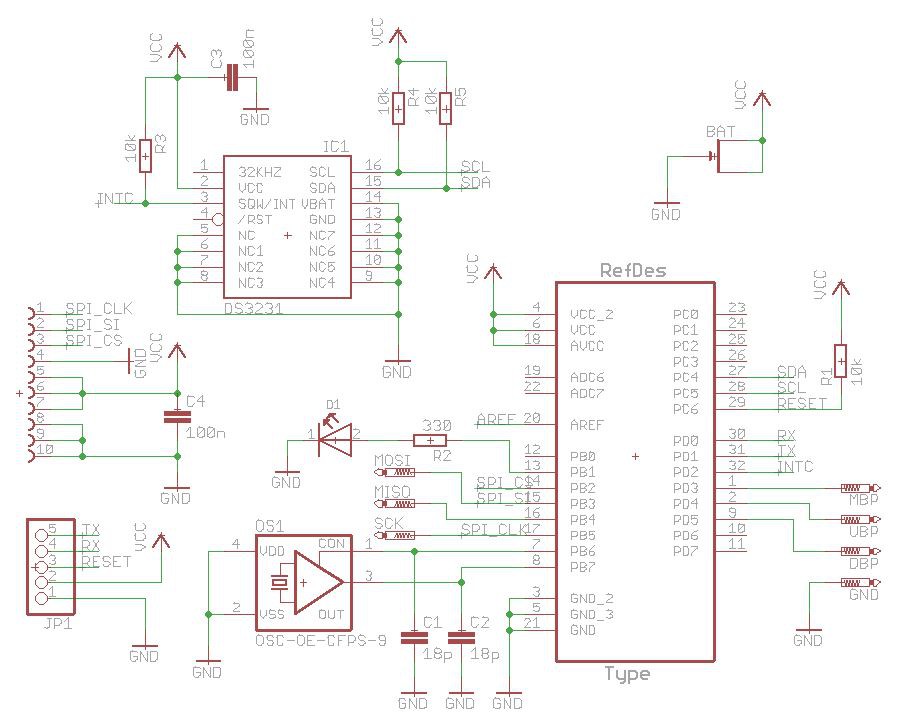
The routing took me a few hours. Mainly because I used relatively thick traces I ended up with dozens of vias. Also, the angles were all over the place. When the board arrived two weeks later, I had very low expectations. But there were no shorts or major design flaws.

The next step was to populate the board. I ordered the components from Farnell. Very fast service and insane packaging even for low quantities like the two Atmegas.

I soldered the board by hand. Thin solder and a flux pen are absolutely necessary for parts like the ZIF connector. For the coin cell mount I cut the metal strip of an old folder to the right length and soldered it to the board.
After burning the bootloader, I used an old Arduino Uno and removed its chip to program the board. It basically worked on the first try without any modifications:
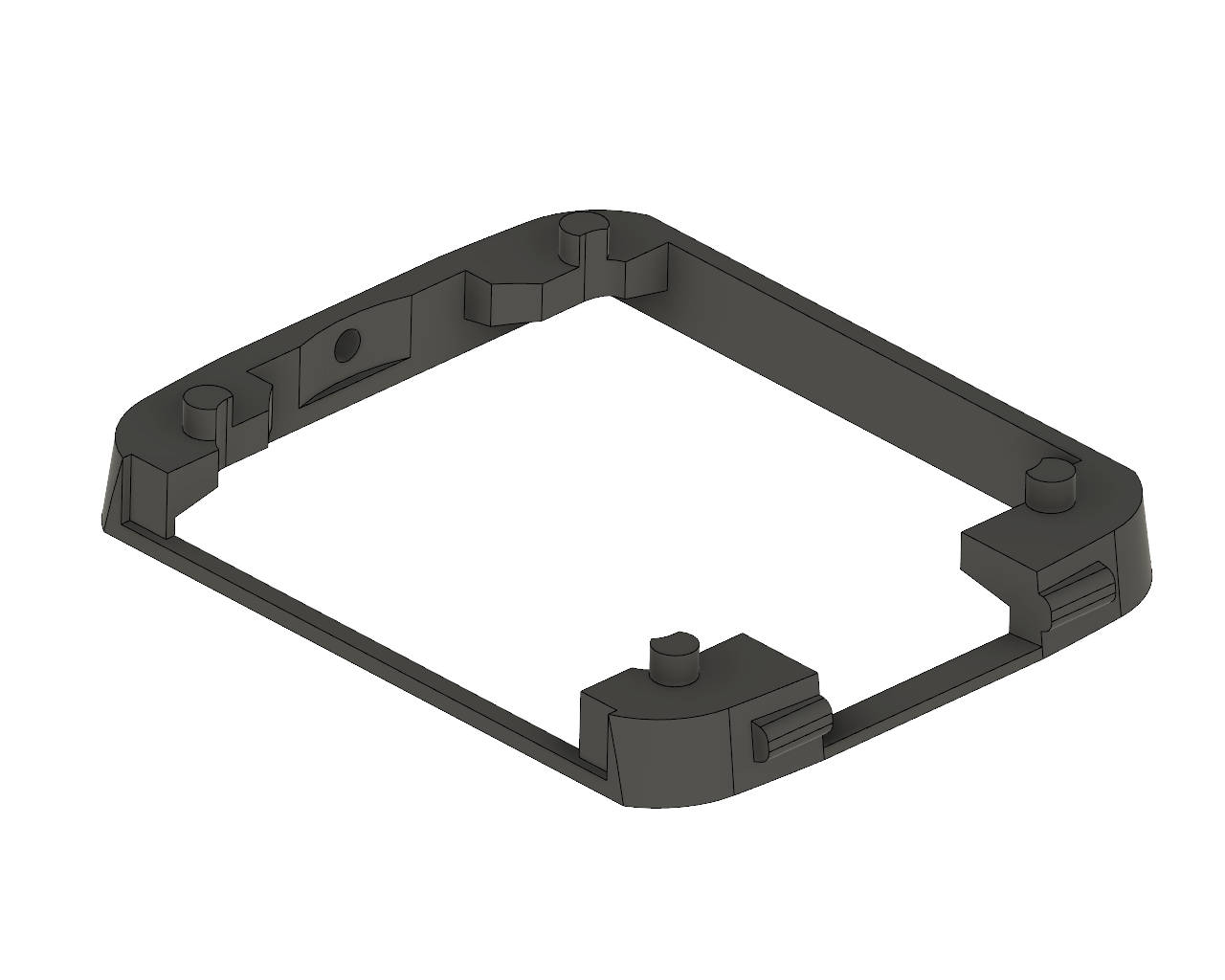
After adding the screen and uploading the code, the watch was already working. To connect the PCB and display, I created a separate printable part.
Although it is functional, the first board has it's problems. The current consumption in standby is still at 450 uA. Also the programming header is only a temporary solution.
Discussions
Become a Hackaday.io Member
Create an account to leave a comment. Already have an account? Log In.
Farnell is known for insane packaging. Once I received 3kg parcel containing nothing but dozen of TQFP parts and a lot of packaging material.
Lovely project, by the way.
Are you sure? yes | no
Thanks! I ordered from Farnell multiple times and it's always like that.
Their packaging is now the main source of silica gel for my 3D printer filament.
Are you sure? yes | no