 agp.cooper
Testing Propagation Delay
I have previously mentioned propagation delay tests using a 5 stage ring oscillator.
So what is that?
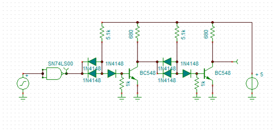
A 5 stage ring oscillator (web.mit.edu):

Here is my implementation:
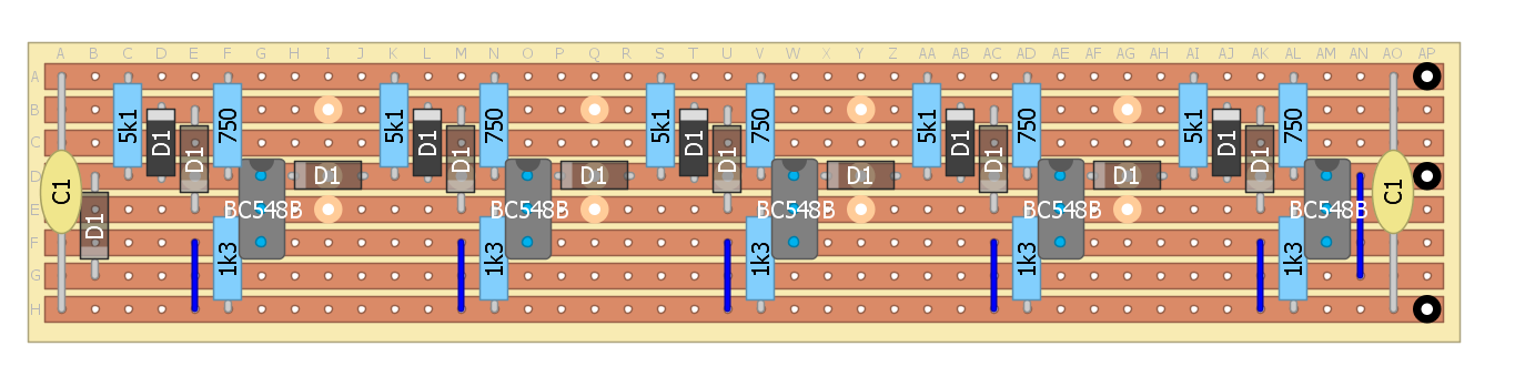
Note: I have not made provision for speed up capacitors in this design but you can work it out.
So to measure propagation delay measure the frequency and then divide the frequency period by 10.
Now you can easily use bread board here if you don't like strip-board.
I used a ring oscillator to check if my base biasing formula worked (and it did):
Rb=0.72*Rs/(Vcc-2*0.62-0.72)
Where Rb is the base drain resistor (1k3 ohms in the above design) and Rs is bias supply resistor (5k1 ohms in the above design).
Nowadays I would use 1k2 ohms and 4k7 ohms as these are easy to get in bulk on Ebay.
If you use a one diode design (2 input NAND gate) then use Rb=0.72*Rs/(Vcc-1*0.62-0.72):
If your interested in a really fast and minimal design consider Johnny Lovqvist's design:
 The only down side with this design is the reduced noise margin (which is a worry if used to build complex circuits).
AlanX
Discussions
Become a Hackaday.io Member
Create an account to leave a comment. Already have an account? Log In.
No problems.
I have seen your Diode Clock. Now that is impressive!
You can run just three inverters if your lazy (use divide by 6).
It is a pain the make them but it makes for easy circuit optimisation.
Check the wave form, you may not get full swing and it may not be symmetrical.
AlanX
Are you sure? yes | no
Trying a ring of three inverters was the *second* thing I did after seeing your post :-)
It turns out that this method is really superior to what I'd been doing. I had been driving the inputs of DDL gates with CMOS gates or 50-ohm signal generators, neither of which is similar to the output of another DDL gate, and the source impedance or voltage levels can affect the results. My previous solution was to chain a bunch of inverters so that at the end, you'd have an accurate DDL signal to drive the device-under-test. With the ring oscillator method, there's no problem at all, because the signal comes from an "infinite" string of inverters.
You'd laugh at the speeds I get, though. 1.99 kHz with 5 gates = 50.3us Tpd.
Are you sure? yes | no
50µs is still better than the 3.5ms of the РЭС15 (russian relays :-D
Are you sure? yes | no
Wow! Thank you for posting this!
I'm testing substitute components for my diode-only logic circuits ( #The Diode Clock ) because some aren't produced anymore, and diodes from various manufacturers may perform differently in my application. I had been checking flip-flop toggle speed and looking at eye diagrams at the end of an inverter chain like this, but hadn't thought of closing the loop to make an oscillator.
I literally ran down to the lab after seeing your post, and guess what - a ring of diode NOR's oscillate! Now I have another way to check prop. delays - and the fastest diode-only oscillator I've made to date!
Great work on your detailed postings!
Are you sure? yes | no