-
BC548B 5 Stage Ring Oscillator
08/02/2016 at 03:10 • 2 commentsBC548B 5 Stage Ring Oscillator
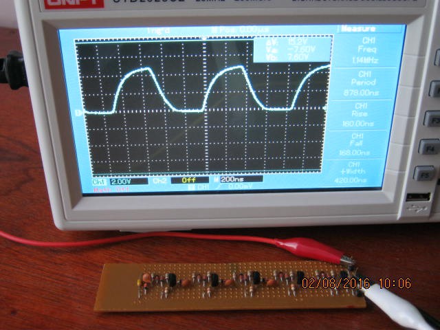
I dug up my old BC548B 5 stage ring oscillator just to compare with the 2N3904 version:
As you can see the propagation delay is about 88 ns (where did I get the 64 ns from, now I remember, I bread boarded a set of BC547Bs recently to check the performace with and without the speed up capcitor) and a nicely formed wave form.The 2N3904 is faster but there is something else is going on?
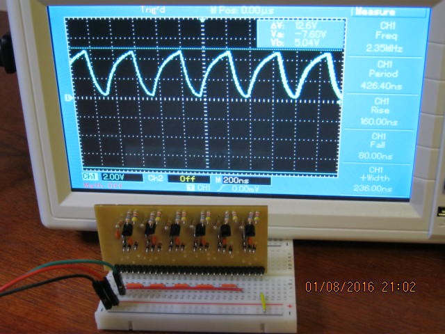
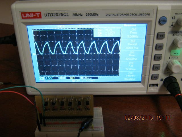
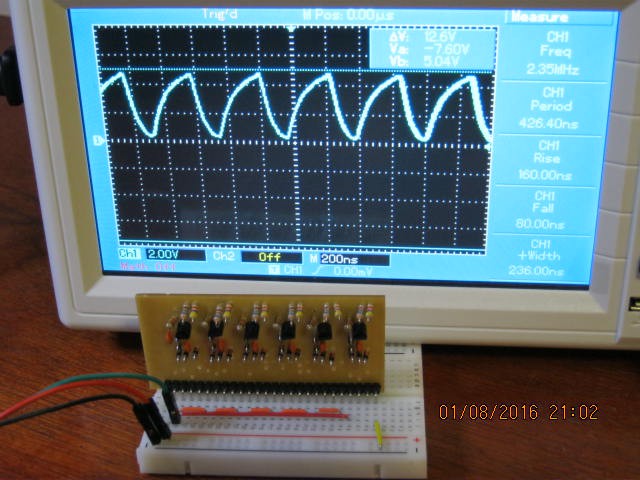
Thinking about this, the propagation delay of the 2N3904 transistors is most definitely much lower than the BC548B transistors. Note the distinct on and off periods of the BC548B and their practical absence for the 2N3904. The main problem here is the slew rate (the rise and fall times) is about the same for both transistors.I decided to increased the base drain resistor from 1k2 ohm to 1k5 ohm. The wave form is now both more symmetrical and faster (3 MHz or 33 ns propagation delay). Now increasing the base drain resistor turns on the transistor a little more when off so the output high voltage is now only about 4 volts (previously about 4.8 volts). This tells me I have pushed this configuration as far as I can without changing the bias feed resistor, the collector resistor or the supply voltage (to stay TTL compatible I don't want to change them):
How good is this simple circuit? A 7400 (TTL) has a nominal propagation delay of 10 ns.
AlanX
-
PCB Isolation and D-Latch/Flip-Flop performance
08/01/2016 at 13:35 • 0 commentsWell I am going to throw away those cheap Chinese PCB boards away. One mistake and the tracks lift. Horrible! But I did get the board finished and tested:
A respectable 42 ns propagation delay but not that much better than a BC548B (64 ns). It falls short of my expectation of 15 ns (as reported by others).
I think the base drain resistor probably needs adjustment. However, I don't think the board will survive a couple of rounds of resistor swaps.
I think I would be better off soldering the link wires (the rows of holes above the pin header) to convert the board into a D-Latch/Flip-Flop and testing that and then make a new board out of a better quality PCB.
In case your wondering how this fits in the with TTL: the above board is currently equivalent to two 74LS10. After the link wires are added it is 1/2 a 74LS74.
AlanX
-
After 35 years of service
07/31/2016 at 06:58 • 0 commentsWell I was complaining about my Weller soldering iron so it spat the dummy.
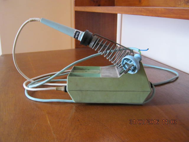
Not really, but I went to plug it in and I got crackle and pop. Unplugging it and the fault was a broken power cable:
My Weller cost $80 in 1981 so in today's money that would be in the order of $400 dollars. I remember that inflation was over 10%, you could get 13% interest at the credit union and a home loan was 17%!
Now my Weller used to have a power switch (long gone), two metal trays (one for stuff and the other for a wet sponge) again, long gone.
It sports a cable burn (hidden behind the power cable) and the power cable cover (PVC) has shrunk exposing the power wires (safe - no exposed copper).
The case is somewhat aged, but the black bakelite iron holder and silicon flexible cable are as good as new.
The soldering tip was replaced (once) after about a month due to using the wet sponge, now I just poke the tip through some paper to clean it and it has lasted 35 years (go figure?).
So I will have to replace the plug and bring it back to life.
The Weller will still need an offsider for the fine work.
In the mean time you will have to wait for the speed test and D-Latch/Flipflop build (assuming you are interested in this thing).
One guy has messaged me to said that the six transistor (DTL) version of the D-Latch works and I note Johnny Lovqvist has gone with the six transistor design for his Discrete Transistor 8080 CPU. So it must work!
AlanX
-
Testing Propagation Delay
07/31/2016 at 01:32 • 4 commentsTesting Propagation Delay
I have previously mentioned propagation delay tests using a 5 stage ring oscillator.
So what is that?
A 5 stage ring oscillator (web.mit.edu):
![]()
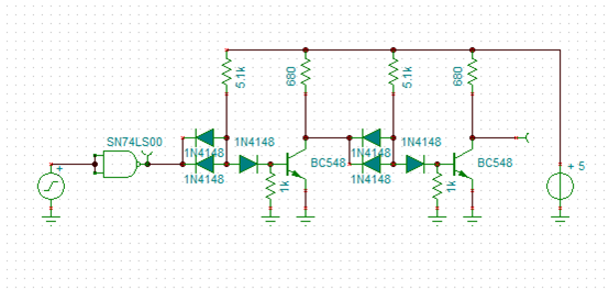
Here is my implementation:
![]()
Note: I have not made provision for speed up capacitors in this design but you can work it out.
So to measure propagation delay measure the frequency and then divide the frequency period by 10.
Now you can easily use bread board here if you don't like strip-board.
I used a ring oscillator to check if my base biasing formula worked (and it did):
Rb=0.72*Rs/(Vcc-2*0.62-0.72)
Where Rb is the base drain resistor (1k3 ohms in the above design) and Rs is bias supply resistor (5k1 ohms in the above design).
Nowadays I would use 1k2 ohms and 4k7 ohms as these are easy to get in bulk on Ebay.
If you use a one diode design (2 input NAND gate) then use Rb=0.72*Rs/(Vcc-1*0.62-0.72):
![]()
If your interested in a really fast and minimal design consider Johnny Lovqvist's design:
![]() The only down side with this design is the reduced noise margin (which is a worry if used to build complex circuits).
The only down side with this design is the reduced noise margin (which is a worry if used to build complex circuits).AlanX
-
A PCB Isolation PCB for a D-Latch/Flipflop
07/30/2016 at 03:50 • 0 commentsPCB Isolation Failure
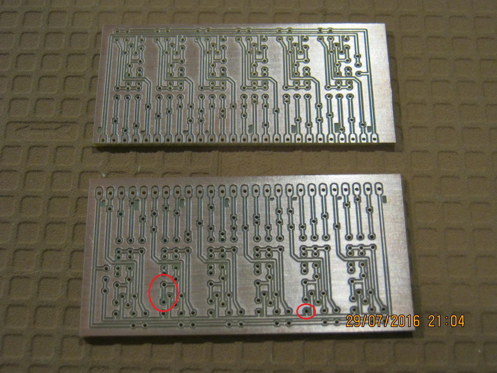
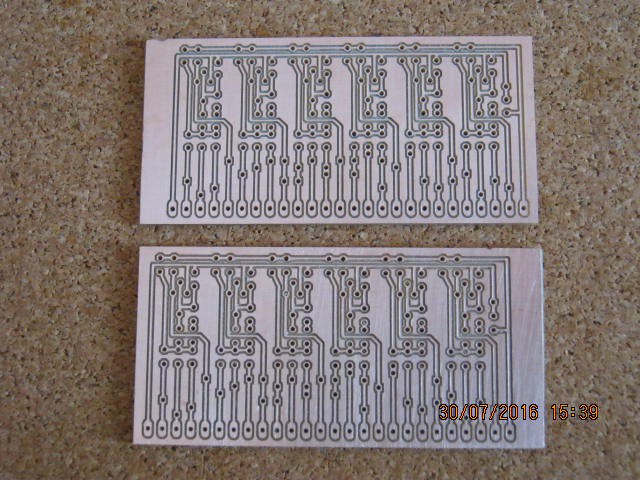
Well I had a few hour too myself (my partner is working a double shift tonight - best not to run my CNC machine wile she is at home) so I found the files and knocked up the gCode file for the D-Latch/Flip-Flop PCB. Double the design up for two boards. Just after I started I realised I had not offset the engraver tool (my macro traces the exact outside of the PCB image). So the tracks and pads will be smaller than planned. Too small to be practical and I scrubbed one off while cleaning the board:
I had some other problems that I have not quite figured out. How to mount the board without it bowing in the middle.
I also need a new soldering iron with a smaller tip. My old Weller is 30 years old, electronics has shrunk in that time but not the old Weller.
I am not going to waste my time with these boards.
Another Attempt
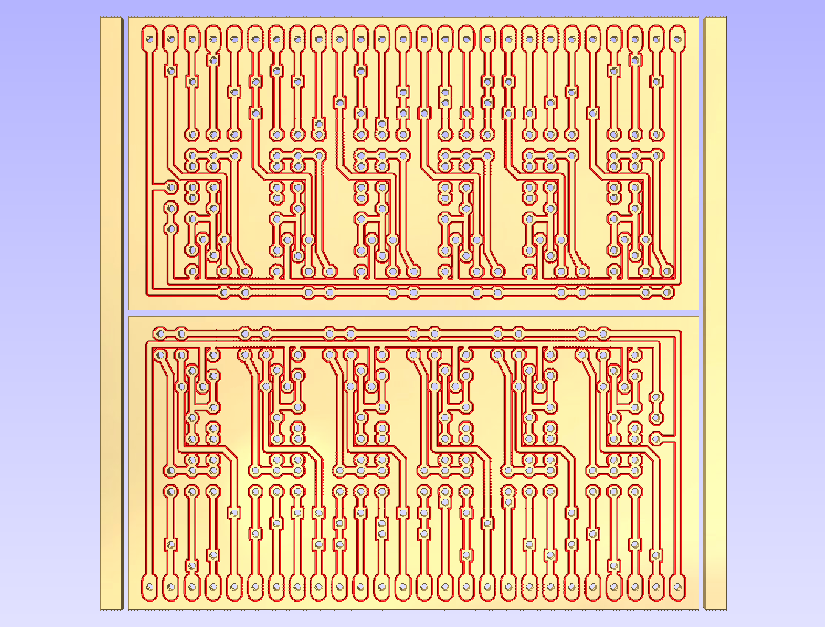
Here is the updated design. This time I added a clamp area left and right, and the isolation is properly offset (~0.1mm):
![]()
Well it is done. Found a few more set up issues that took some time to resolve:
This cheap Chinese PCB (about $0.50 per 3" x 4") is a bit fragile. May be better to pay a bit more money for better quality.
AlanX
-
Discrete Dual Quad NAND using PCB Isolation
07/30/2016 at 03:42 • 0 commentsPCB Isolation
I recently revisited the design using a PCB rather than a prototype board.
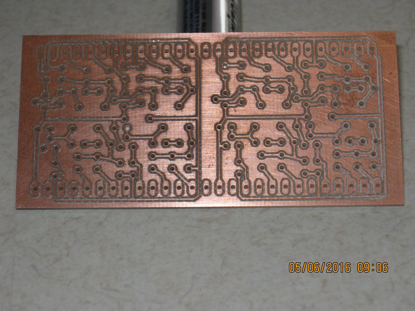
Here is board after milling:
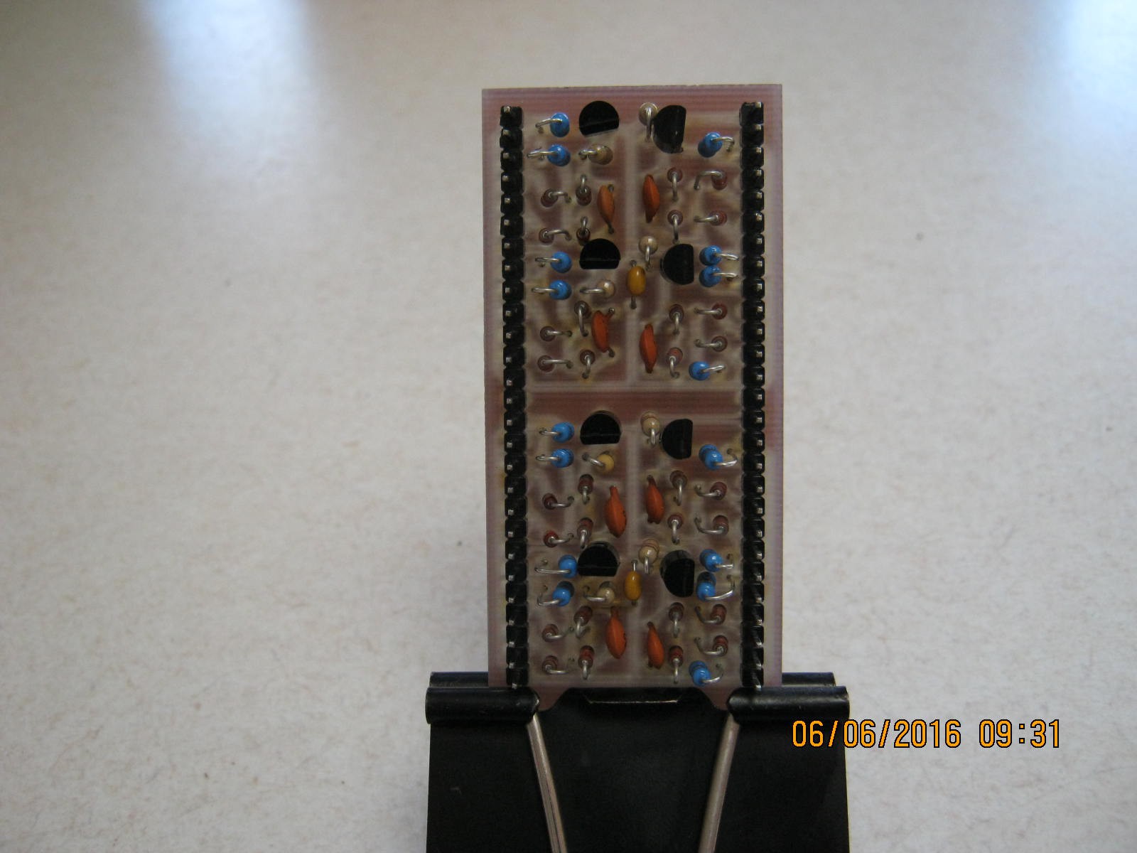
Here is the complete board with eight NAND gates:
Want to build a Discrete Transistor CPU?
If you have ever contemplate building a transistor CPU, one approach is to design simple building block.
Here is a six 3 input nand gates that can be configured as a D-Latch or a flipflop.
You will need about 150 of these as a minimum (about 800 for an Intel 8080).![A 6 gate D-Latch]()
Hers is my board design (the components values are as discussed in this page):
![]()
If you have not realised the top red links are actually wire links (the board is actually single sided).
After cruising the Internet another "transistor logic" guy has build one of these (I can't re-find the webpage) and says that it does not work and recommends the 9 gate version. That suggests I will have to build a couple to check.
Another "transistor logic" guy says the 2N3904 is much faster (x4) than the BC548. So why not go for a 2N3904 version (its a common garden variety).
Just waiting now on delivery of a resistors/capacitors and transistors.
Just have to check the 2N3904 pin-outs before finalising the board.
Regards AlanX
A Discrete Transistor 7400 NAND GATE
If we did not have ICs then this is what a 7400 NAND gate would look like!
 agp.cooper