Andrew Becker
-
Hurry up and wait
06/10/2014 at 20:52 • 0 commentsThe first lot of components has been drawn and ordered, as have the bearings, pulleys and belts. So now I'm just waiting for the first lot to arrive and in the mean time I've been tinkering with the electronics and control side. As you can imagine setting the arm up for 3 axis motion is a case of rudimentary geometry, and the 4 axis case is only slightly more challenging. The addition of the 5th axis is where things get exciting. The 5th axis capability gets added as an axial rotary joint between the second and third major joints and the movement of this one joint changes all of the Cartesian coordinates of the endpoint (in all but a few special cases).
-
Slow Progress
06/05/2014 at 21:44 • 0 commentsSo I've been as sick as a dog and wrapped up in bed at home. This might have been a great opportunity to get a whole lot of work done on the project but if I had been well enough to do that I would have been well enough to go to work since I work as a design engineer doing CAD work. Still, between sleeping and feeling sorry for myself I managed to place most of the fasteners and finish off the 5th axis. I also found a nema 8 motor and gearbox combination that will work perfectly for the 6th axis but the supplier is out of stock so I'm leaving the 6th axis for now.
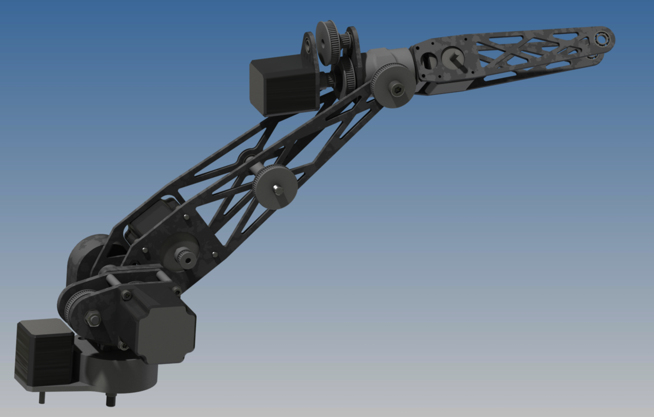
![]()
I am going to box the arms for additional rigidity, other than that the design is at a stage where I can begin to manufacture components. Most of the design is laser/water jet cut parts however there are 6 or 7 components that will need turning or in the case of 2 components 4 axis milling. This sounds more complex than it actually as as the 4th axis movement will just be indexing 90* on a rotary table. I believe that all of the components designed can be manufactured by an enthusiast with a bit of patience and inventiveness.
Below is the initial BOM to give you an Idea of what will be used. This doesn't yet include any electronics, prices, or part numbers.
Item QTY Name 1 1 RA1001 2 2 0.5Nm Stepper 3 1 Stepper 0 Mounting Plate 4 1 Pivot 0 Pin 5 2 DIN 628 SKF - SKF 3203 A 6 1 Pivot 1 Base 7 1 Pivot 1 Pin 8 2 ISO 4032 - M16 9 2 1Nm Stepper 10 4 ISO 4762 - M6 x 20 11 1 DIN 625 SKF - SKF 16100 12 4 GT2 20T 13 3 GT2 60T 14 1 DIN 472 - 40 x 2 15 3 GT2 20T Narrow 16 3 GT2 60T Idle 17 1 Joint 1 Spacer 18 2 Joint 1 Gearbox Plate 19 10 DIN 625 SKF - SKF 618/8 20 1 ISO 4762 - M6 x 12 21 1 Gearbox Shaft 22 1 Arm 1 Mount Side 2 23 2 ISO 4032 - M8 24 1 Joint 1 Bush 25 1 Joint 2 Clevice 26 2 DIN 628 SKF - SKF 7202 BE 27 1 Joint 3 Axial Pin 28 1 Arm 1 Back Side 29 1 ISO 4762 - M8 x 80 30 4 DIN 125 - A 8.4 31 1 GT2 60T Threaded 32 1 8mm Bush 33 4 ISO 4762 - M5 x 16 34 1 ISO 4762 - M8 x 30 35 1 ISO 4762 - M8 x 16 36 4 ISO 4762 - M5 x 50 37 4 Joint 1 Gearbox Bush 38 2 Joint 2 Gearbox Plate 39 1 0.25Nm Stepper 40 2 Arm 2 Motor Side 41 1 Joint 5 Pivot 42 2 DIN 625 SKF - SKF 618/6 43 4 ISO 4762 - M4 x 12 44 4 ISO 4762 - M3 x 10 45 1 ISO 4762 - M6 x 16 46 2 ISO 7089 - 6 - 140 HV 47 1 ISO 4762 - M6 x 10 48 1 Arm 3 Tube 49 1 Arm 3 Pivot -
Performance Considerations
06/04/2014 at 19:24 • 0 commentsWith the detailing of the model it is now clear that due to the weight of the arm (current conservative estimate about 8 kg total) I am going to need more power to drive joint 1. With a bit of investigation I found that a 3 Nm Nema 23 motor is readily available as a direct drop in replacement for the motor I was planning on using however it will require a higher amperage driver. In addition I have dropped the size on the joint 5 motor to 0.25 Nm as driving through a 4:1 ratio on a 100 mm arm will just handle the target load. If you haven't guessed by now I plan on running the steppers at the absolute limit of their rated capacities and maybe a bit beyond, I don't want to have any potential performance unused.
-
Closing in on a Design
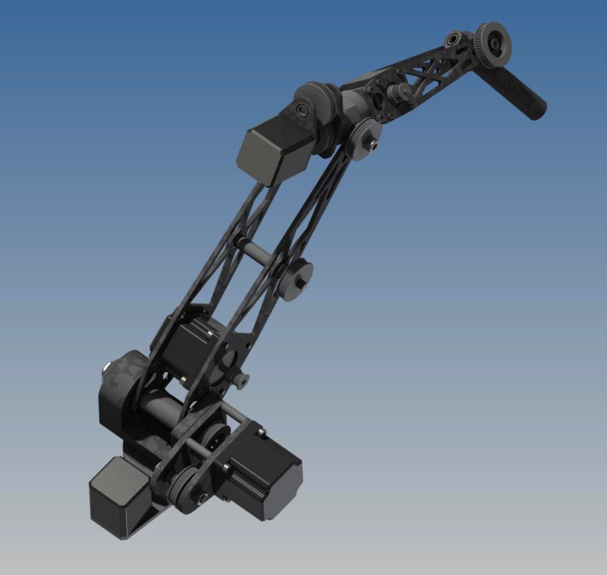
06/04/2014 at 19:02 • 0 commentsSo I've been working on the layout for the arm to ensure that I will be able to expand it to 6-axis eventually and I've been adding a whole lot of detail as I said in the previous post. You can see below the 'wrist' joint before arm 2 as well as the addition of most of the bolts, nuts and bearings. This will make a full B.O.M. easy to produce.
![]()
The pulley gearboxes are less than ideal however the design has been done so that I can swap in high precision planetary gearboxes at a later stage. These cost around $250 a piece so they will be the last items to buy if the budget allows. They should be lighter than all of the pulley gearbox components with less backlash.
-
Detail Work
06/04/2014 at 12:12 • 0 commentsI have an opportunity today to put in some decent hours on the project so I'm trying to get through the detailed mechanical work. It's one thing to say "it will work like this" and something completely different to have every part, nut, bolt, washer, and bearing fit together correctly with the right tolerances. I am very fortunate to have a full copy of Autodesk Product Design Suite which includes Inventor. In my humble opinion, having also worked with Solid Works, Catia and Solid Edge, it is the best design package available. It requires plenty of attention to detail but if done properly it will produce an up to date set of drawings, exploded views and B.O.M's with part numbers, weights and quantities all from one assembly. It also allows motion simulation of the assembly with exporting of loads to F.E.A. I will try post a video of this some time.
So most of today will be dedicated to detail work on the design to ensure that the CAD model will be properly representative of what I am building.
-
Major Changes
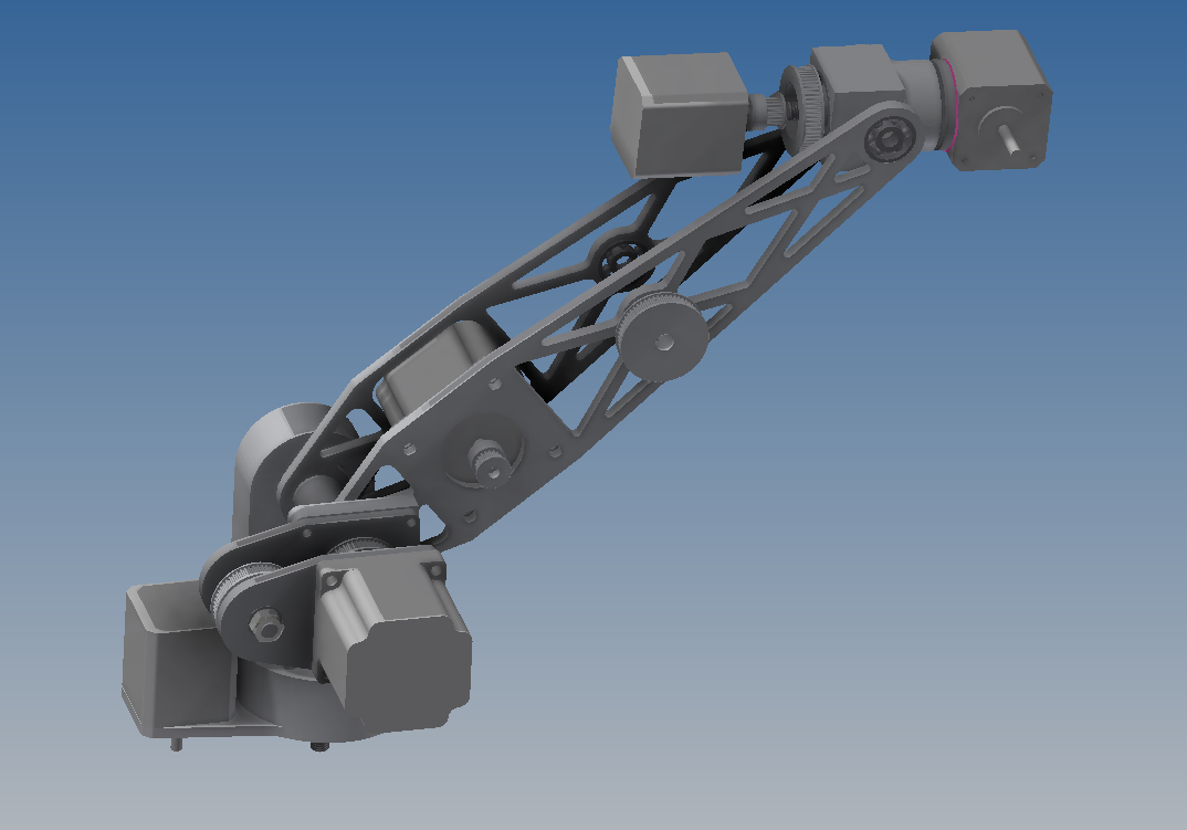
06/03/2014 at 22:20 • 0 commentsIt took me much longer than I hoped but I have made the changes detailed below (sorry for the double post) and the arm now looks something like this (a bit more complete than shown):
![]()
As you can see the rotation motor should counterbalance the 2nd arm somewhat however it will greatly increase the load on the primary joint. I have two options:
1) More ratio in the first gearbox - slower movement but easy to change
2) A second motor - Same speed but more complex to implement
Speed is a priority so I will probably go with the second one.
Despite a number of concepts that I eventually discarded I am glad I did the exercise as the layout concept can be extended to joints 5 & 6 too just with smaller motors. It's too late now to detail the hardware that I have purchased like I hoped but I am slowly adding it all to the BOM so check it out if you're interested. Nothing too fancy yet but once the arm is moving I'll start playing around with connected control.
-
Thoughts
06/03/2014 at 15:55 • 0 commentsI was brainstorming at work today and have decided to add an axial rotary joint on arm 2 as close as possible to joint 2 This is the joint required to make the arm 5 axis. At first I am going to lock this joint but adding it from scratch at a later stage will require significant redesign and that will be counter productive. As a result I am going to spend a large part of tonight re designing from joint 2 onwards rather than producing the remainder of the drawings. Hopefully I will have quite a bit to log in about 5 hours time :)
-
Progress so far
06/02/2014 at 20:49 • 0 commentsI started this project before I discovered Hackaday so I'm going to quickly summarise what I have done so far. If I miss anything or if it is unclear what I'm doing please let me know and I'll try update it. I will try to post enough pics to clarify as I go.
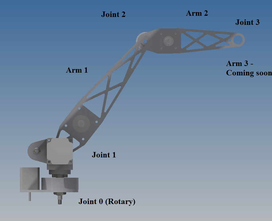
Layout and nomenclature as follows:
![]()
I started by roughly estimating the lengths and therefore the torques required for each joint. I decided on the following:
Arm 1: 300mm
Arm 2: 200mm
Arm 3: 100mm
This will suffice for a 4 axis prototype with 500mm of reach and 600mm with the 4th axis co-linear rather than perpendicular.
This means that if I want to not just hold but lift 1kg at 500mm I would need roughly 5Nm at joint 0 plus whatever torque is required for acceleration and a bit of FOS (factor of safety). Assuming an acceleration of 1g and a factor of safety of 1.5 we need around 15Nm. I know from previous experience (a 4 axis CNC mill) that linux CNC can reliably step at a rate of around 20kHz with great torque. On a stepper running a 10 microstepping driver board and 200 ppr (pulses per revolution) that is 10 revolutions per second or 600 RPM. I want a speed of around Pi rad/s or 0.5rev/s. That is 20 RPM so we can run a reduction box with a ratio of 20:1 however a 1Nm motor is a workable size so I decided to run a 16 to 1 ratio. It might turn out too fast and not powerful enough, especially considering that I'm not yet taking the arm weight into account which will be significant. As a resault am also going to make provision to use 2 motors on Joint 1 in case the gearing is too 'low' for the payload I want.There will also be time taken to accelerate the arm and decelerate it so the effective speed will be much less than this.
Joint 2 will be pretty much spot on half of joint 1 however I felt that for simplicity I would use the same motor and for the most part the same gearing. I am using custom belt drive gearboxes since low backlash planetary boxes are pricey so for the two joints I'll change the pulley sizes to customise the speed and torque. The quickly available ratios for me are 16T, 20T, 40T and 60T (local robotics shop) so there is a decent spread. I will CNC custom ratios if I need but I doubt it.
At this stage I'm not too concerned about joint 3 because the arm length is so short that I barely need 2Nm and I have some decent Nema 17 0.5Nm 200 ppr steppers I can use. With a 4:1 pulley drive this will be perfect.
So to summarise so far:
Joint 1: 1Nm Stepper 16:1 ratio
Joint 2: 1Nm Stepper 12:1 ratio
Joint 3 : 0.5Nm Stepper 4:1 ratio
I have to complete some drawings now so that I can have parts made before the weekend so next update will be tomorrow night. As a teaser I already have the steppers, drivers, pc interface board, power supply, pulleys and belts and some manufacturing drawings.
HIGH PERFORMANCE ROBOTIC ARM
An affordable 4/5/6 axis robotic arm design that can be easily made by students/enthusiasts developing for real world interaction.