 Uriel Katz
So now that I had the connectors mapped the first step was to connect the stepper motor drivers and set the correct current limit.
The current for the motors is (according to this and other sources):
X,Y, Extruder - 0.83A
Z - 0.4A
Setting the current limit for A4988 drivers is explained there too.
After setting up the stepper motor drivers I proceeded to using a test program (can be found in the files section) with the RAMPS board with to see that I can actually control the steppers:
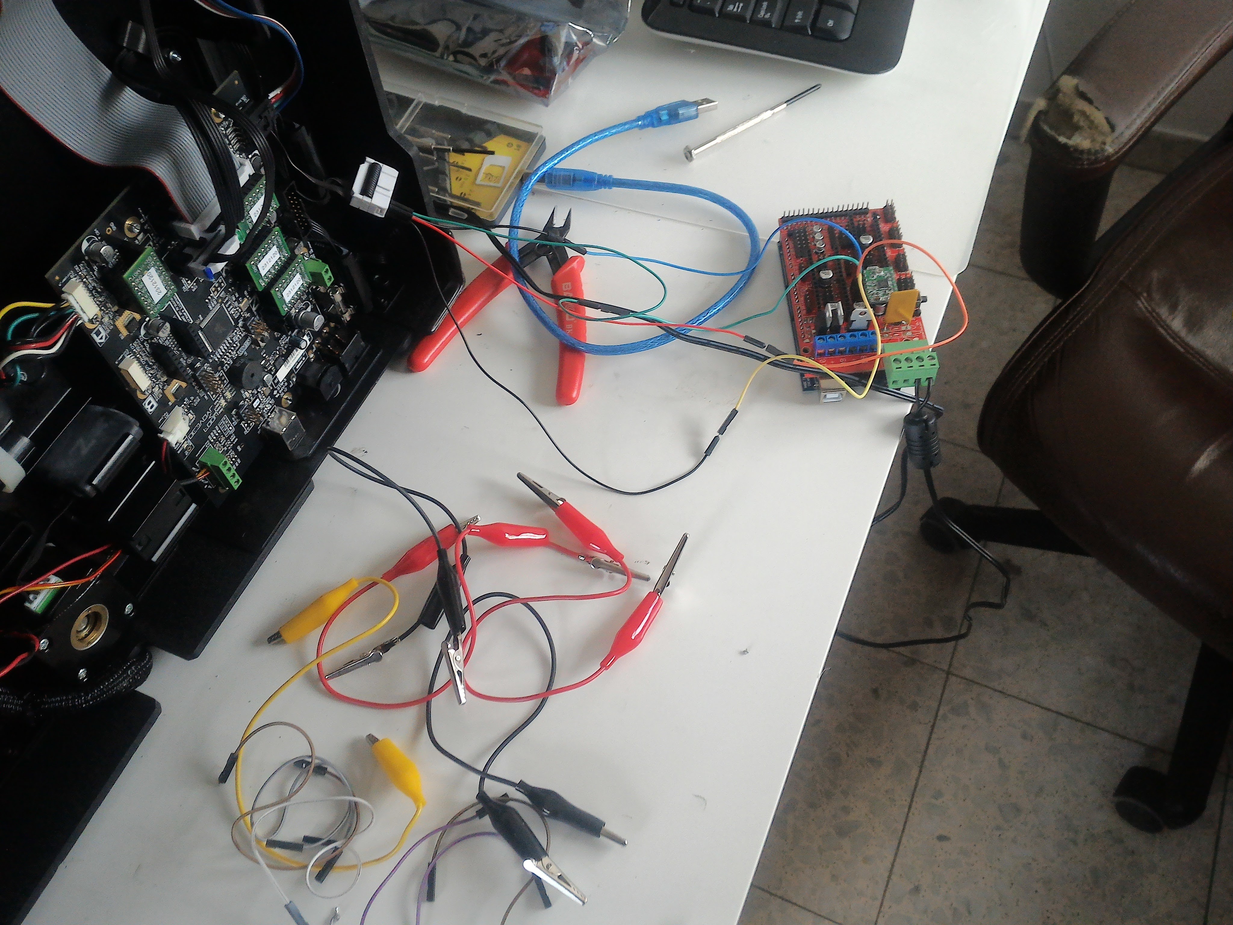
At first I used a 12V PSU (with only 1.5A!) for testing as the RAMPS board doesn't support 24V natively.
Next were the endstops using a cell battery and a multimeter in diode/conductive test mode:
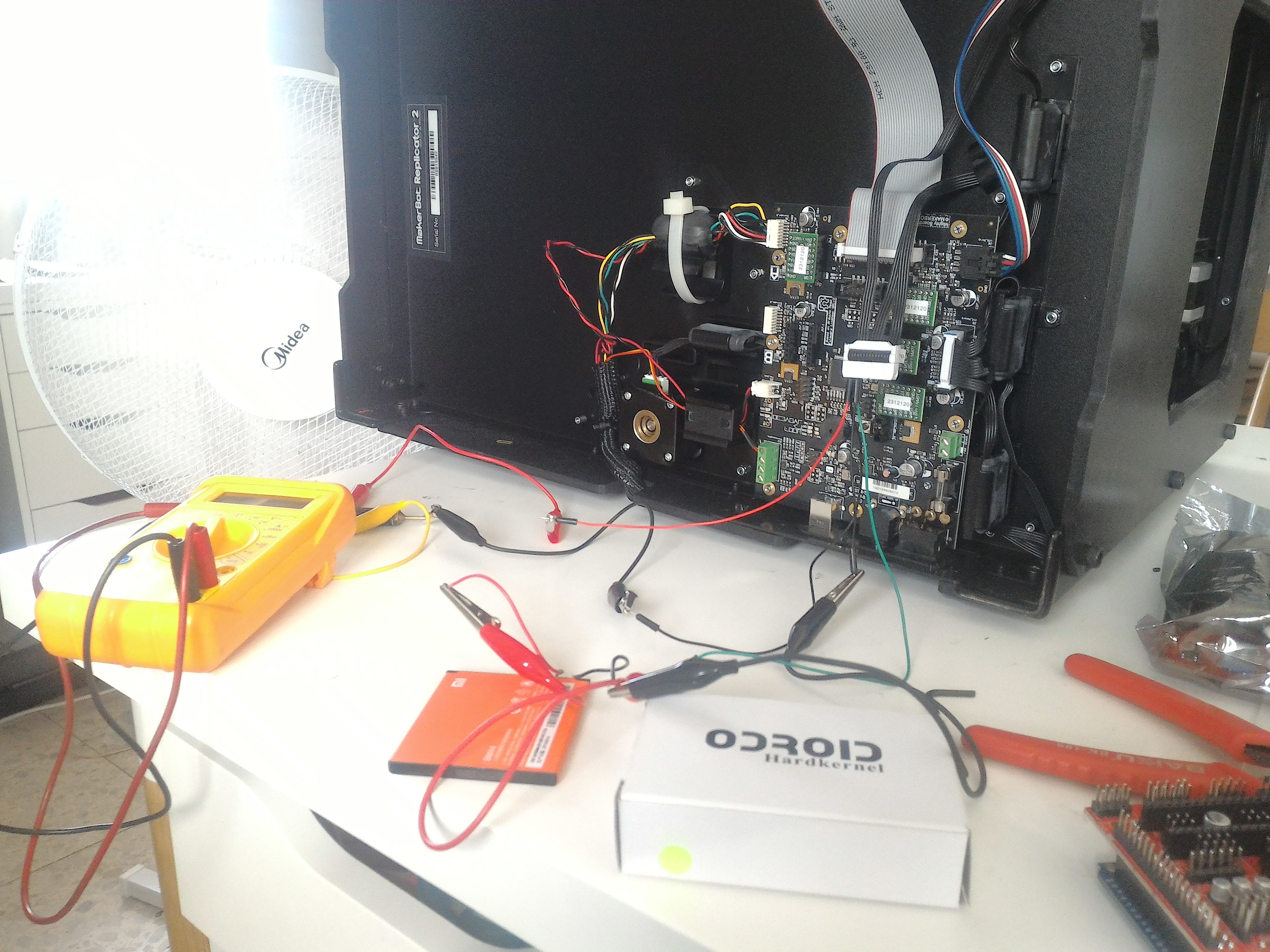
G - is connected to multimeter and battery ground
V - is connected to battery positive
When the endstop is triggered a light will go off and the tester will beep.
I did this instead of connecting it to the RAMPS board for testing because:
1. If I mapped wrongly the pins I could harm the arduino board (there is no protection)
2. It was easier than changing the testing code to blink a led/send via serial
Now that I knew all the mappings were correct I proceed to working with 24V instead of 12V, That required to:
- Make sure all your caps are rated above 24, ideally 50V (to be super safe) but mine had 35V which is just good enough
- Disconnect diode D2 (see this) this is used to provide power the Arduino from the 12V power, but since we are using 24V we can't use this as this will fry the board.
- Disconnect the 11A fuse, this fuse is rated for 16V and is not needed since it is only used for the heatbed (D8 output in RAMPS board), it is not necessary to really take it out but just in case I make a mistake and put power into the other power connector it won't mess up the fuse.
Now the board can work perfectly from 24V but the Arduino needs to be powered separately.
I had to cut the connector of the power supply so I could connect it directly to RAMPS, the inside of the wire is positive and the outside is negative.
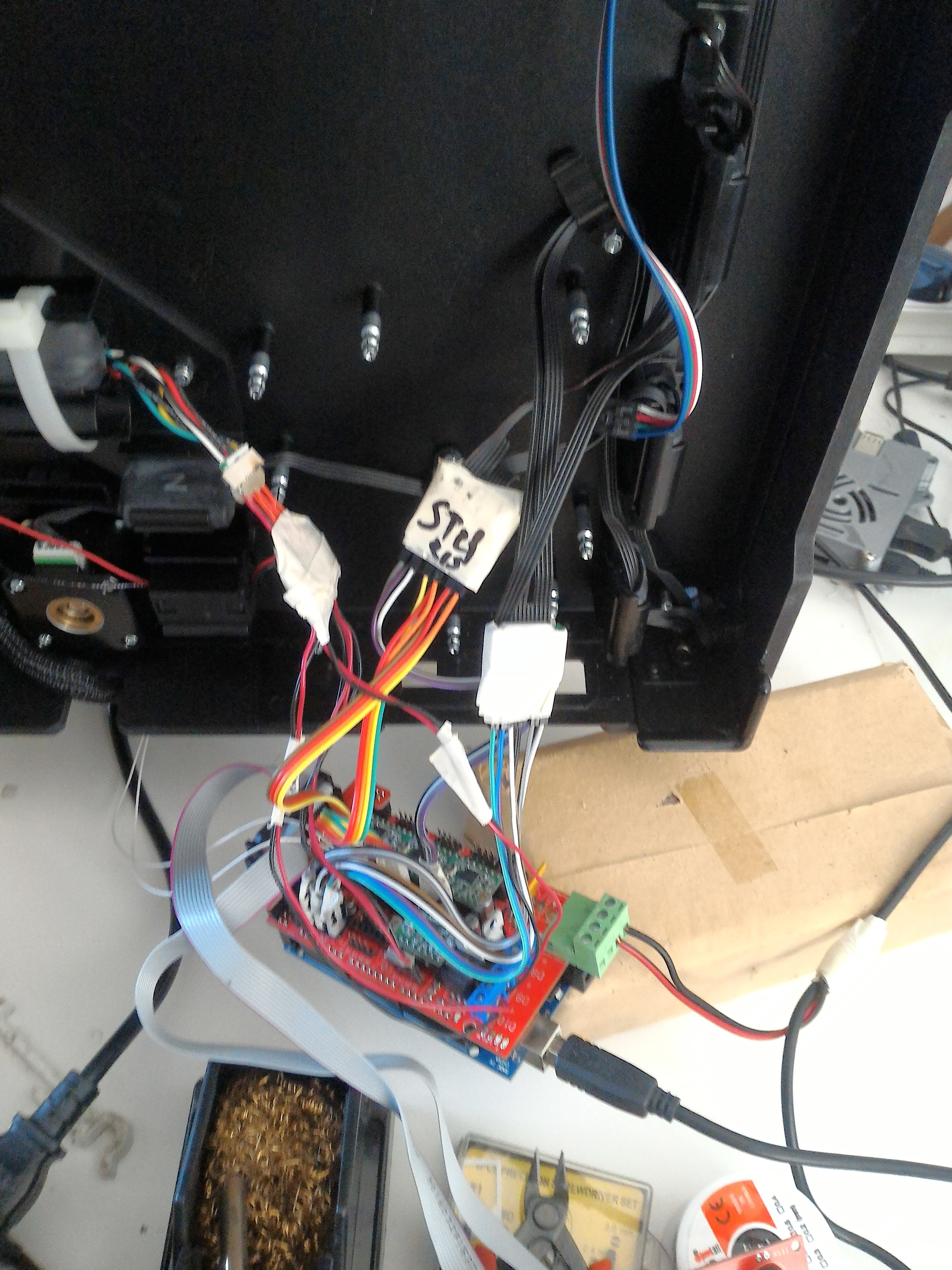
Now that I had all the parts working ad-hoc I proceed with making an adapter board from Makerbot connectors to RAMPS connectors that looked like this:
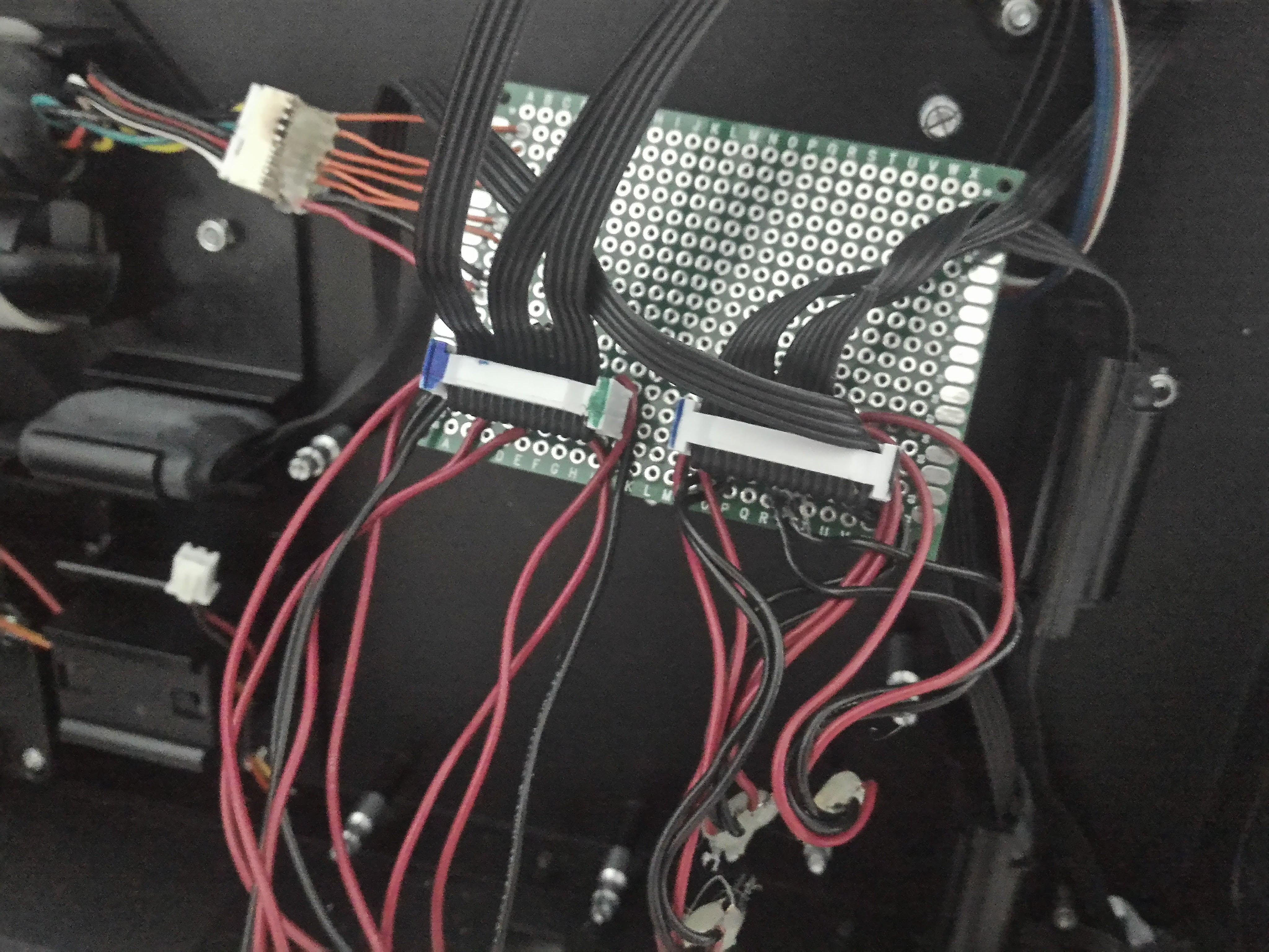
It basically adapts the steppers, endstop and extruder connectors of the replicator 2 to individual connectors for the RAMPS board.
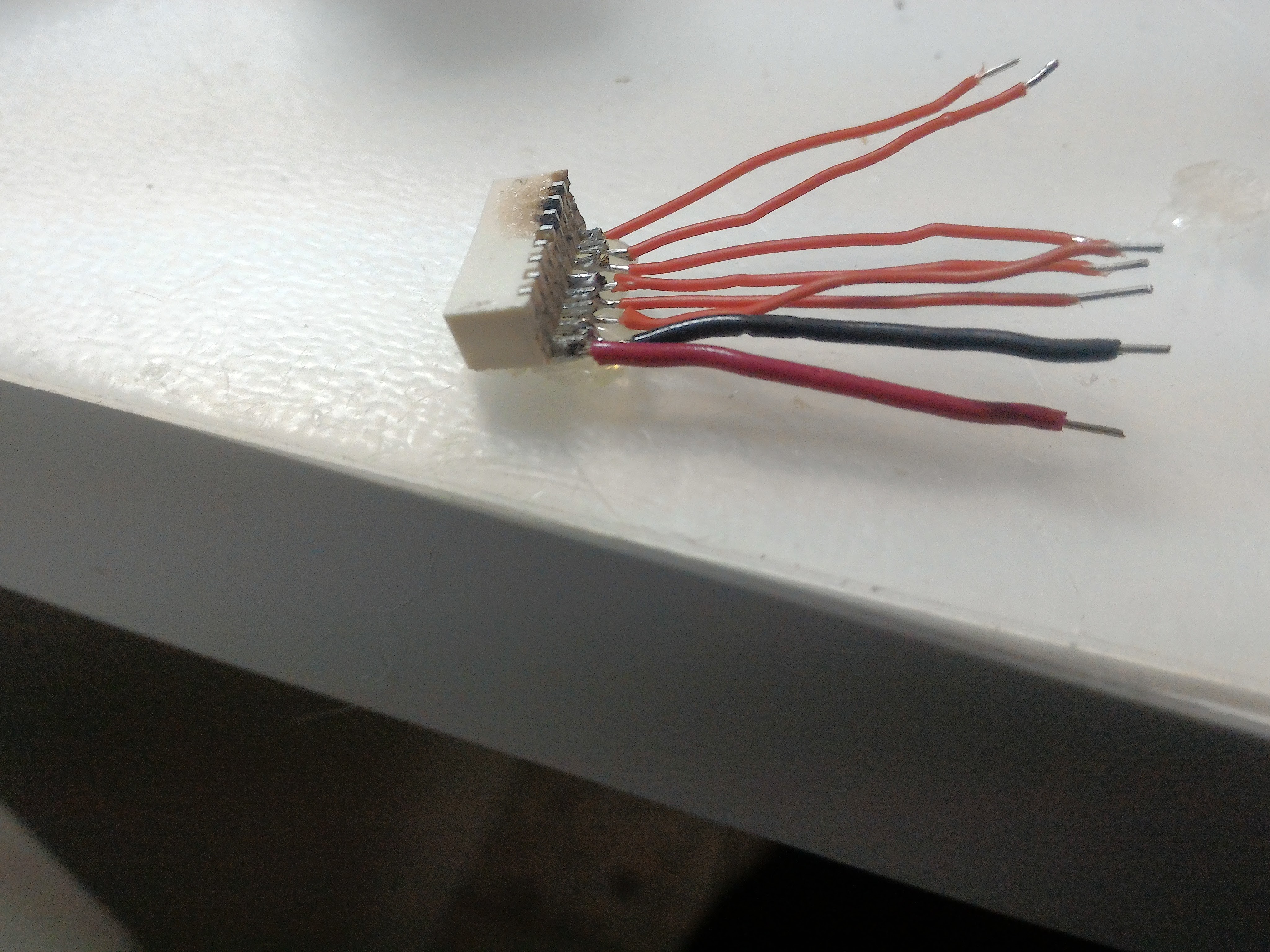
The connector on the left is actually taken from the original board and is used originally for the second extruder:
While the adapter board worked it was a PITA to solder and took a lot of space, so I changed my approach to using male-to-female cables that I just received after finishing the adapter board and some tape to hold them more securely and it is been working perfectly:
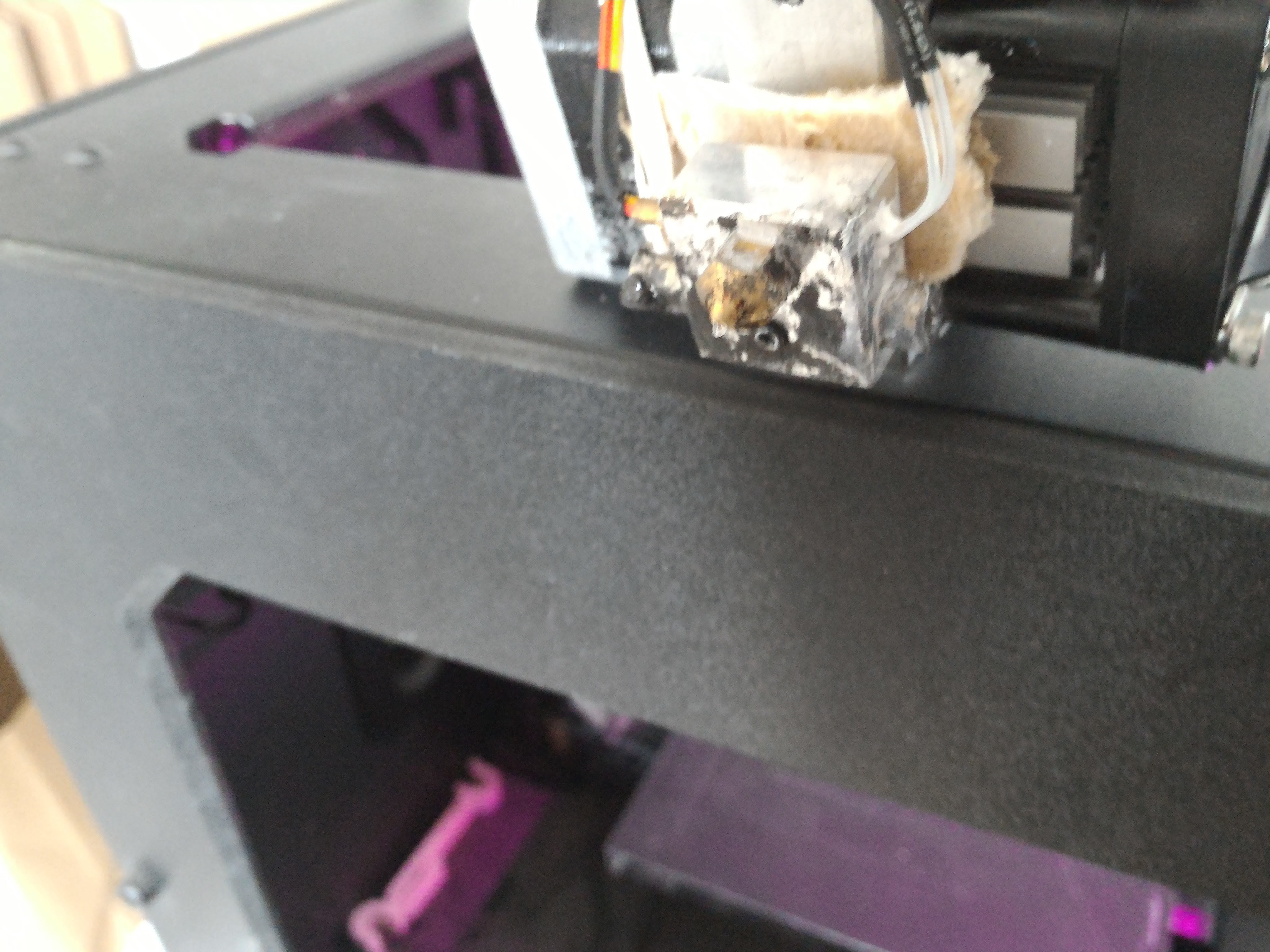
Another thing that need adapting is using a thermistor instead of the thermocouple, since I wanted to change as few as possible in the printer I added the thermistor in hole on the opposite side of the thermocouple with the help of (alot) of thermal paste and kapton tape (not shown in this picture):
With all the parts wired the next step was configuring & installing Marlin :)
Discussions
Become a Hackaday.io Member
Create an account to leave a comment. Already have an account? Log In.