 Adrian Georgescu
For our final technical project we decided to build an electric go kart using commonly available components. The requirements were to implement project management principles, hardware, and software design. The project build time was about 3 months, but the research started about 4 mounts in advance.
We started to research potential motors that could be suitable for a go kart. Our target motor power output was 3kW. The majority of 3 phase 3kW electric motor are priced around $400, which was too expensive for our budget. We settled on converting a car alternator to a 3 phase synchronous motor. Picked one up for about $30.
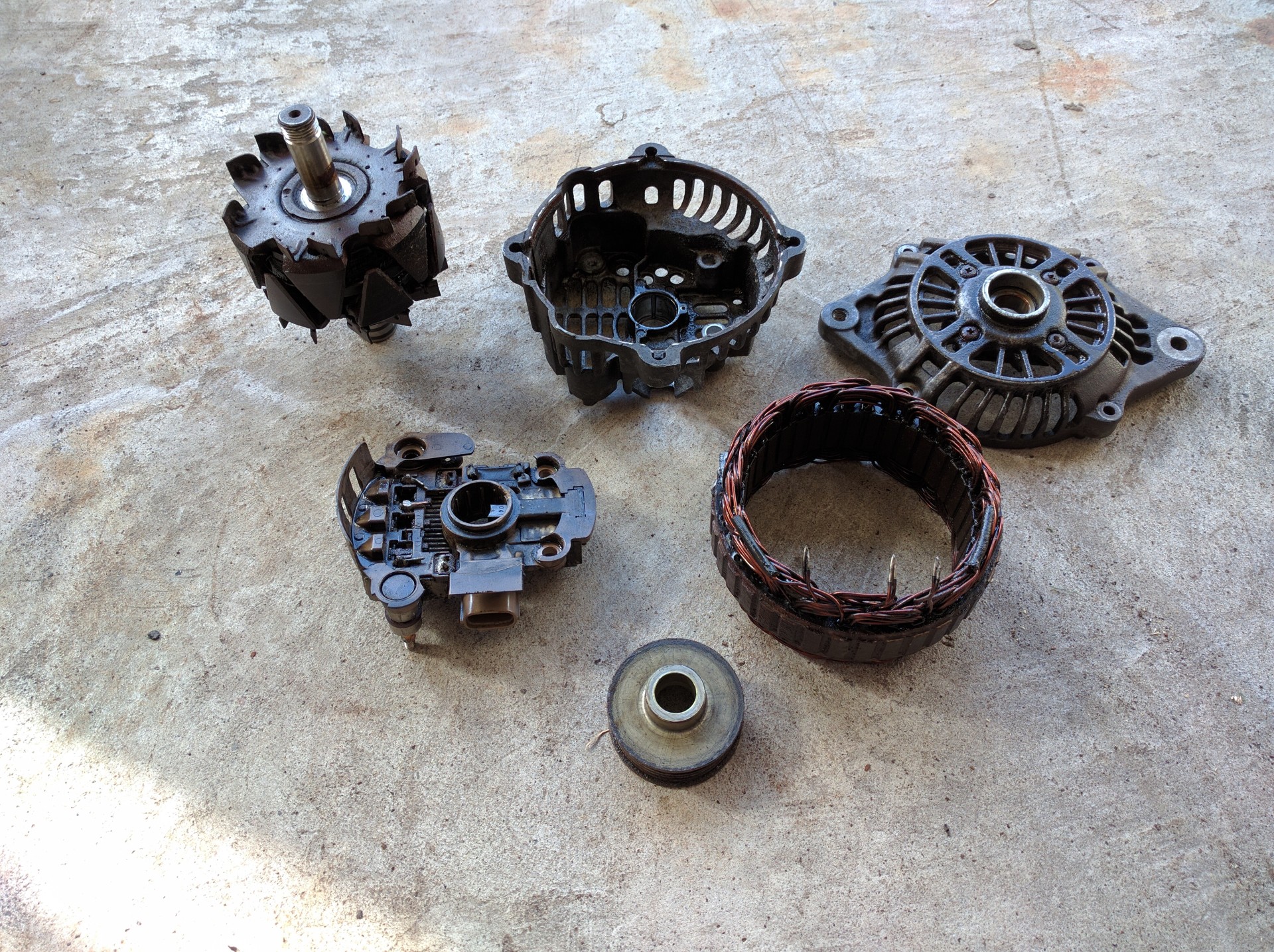
Here is the alternator disassembled, bridge rectifier and regulator disconnected. We also soldered 2 wires to the field coil brushes.
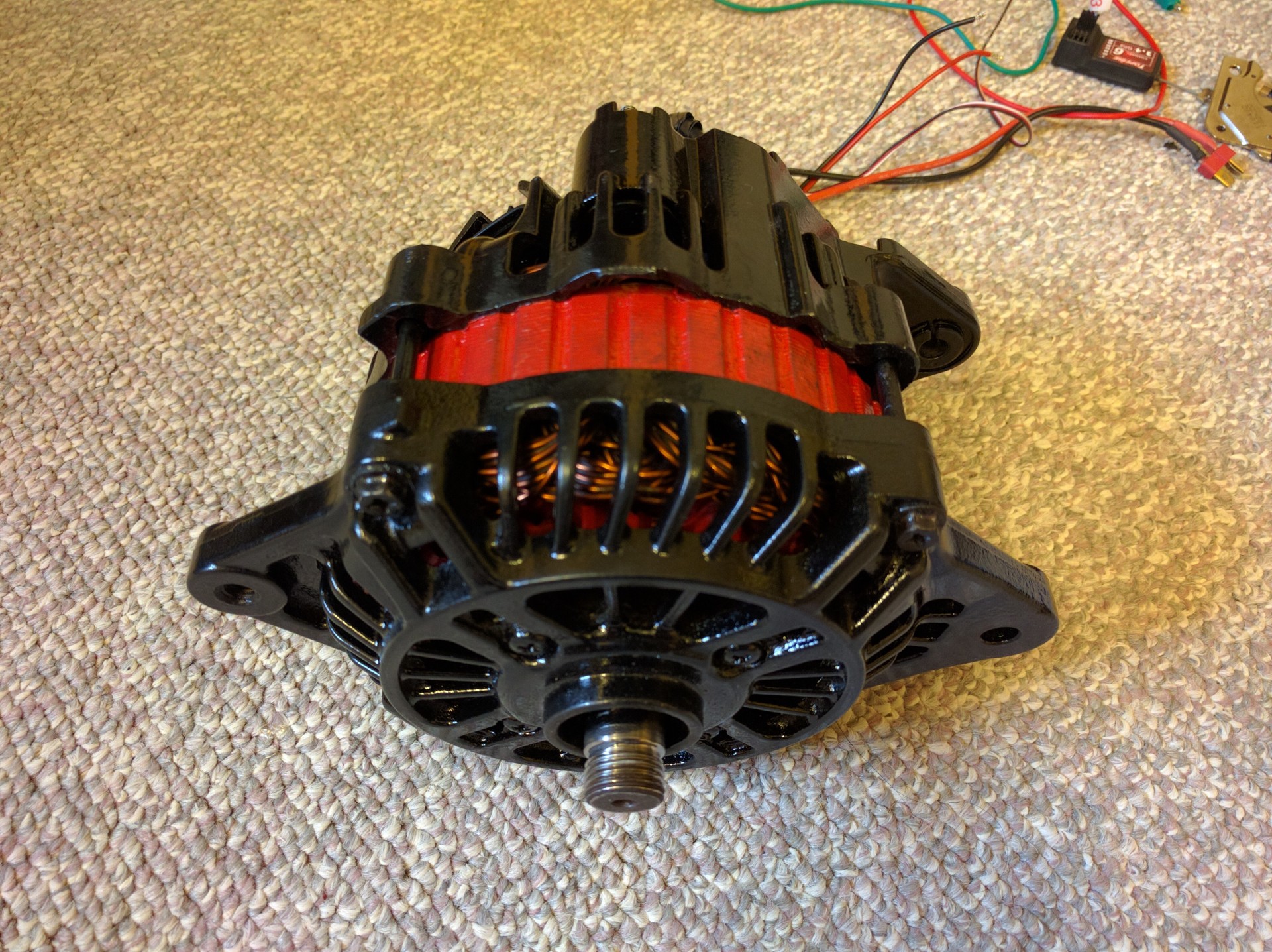
Alternator painted and reassembled. Here we tested it using an RC airplane ESC.
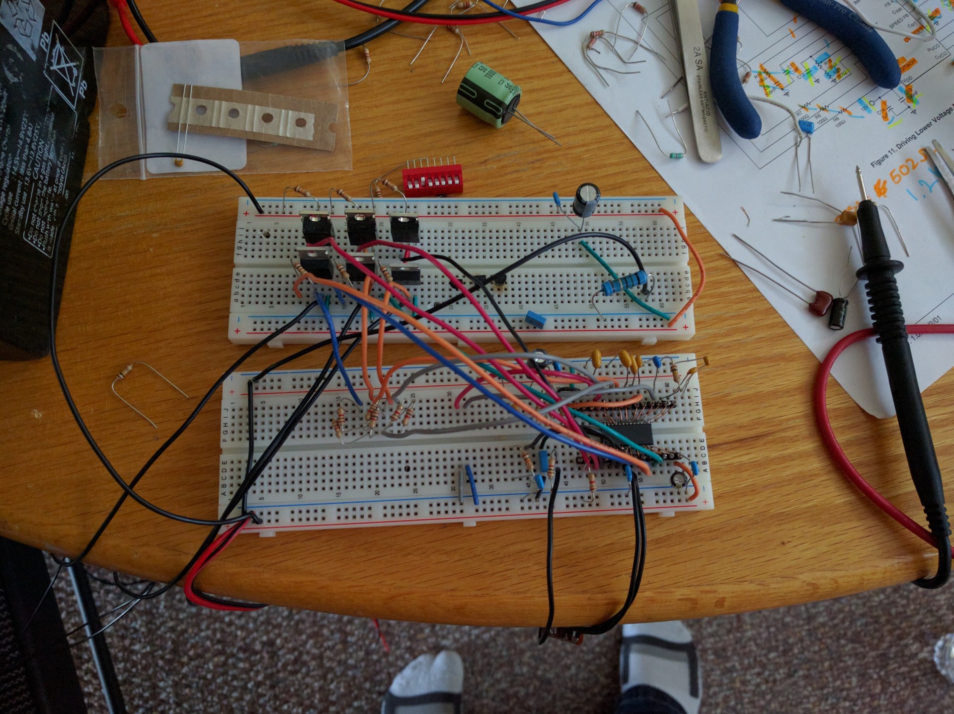
Next we tried to build a variable frequency drive using the ML4425CS motor controller. Nice little chip which has a back emf decoding.
The solution to this problem was to purchase a commercial 3 phase motor controller, intended to be used on electric scooters.
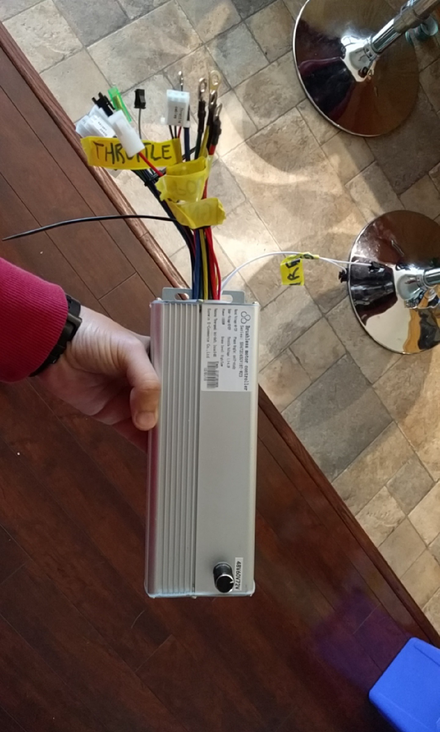
This particular controller has a wide voltage input (48V to 72V) and can handle 1.5kW continuously and 3kW peak. It also has a 40A current cutoff. We tested it with the modified alternator and worked very well.
Next we needed a lightweight battery, up to this point we were using 4 lead acid car batteries, which had a mass of about 80kg. They were not practical.
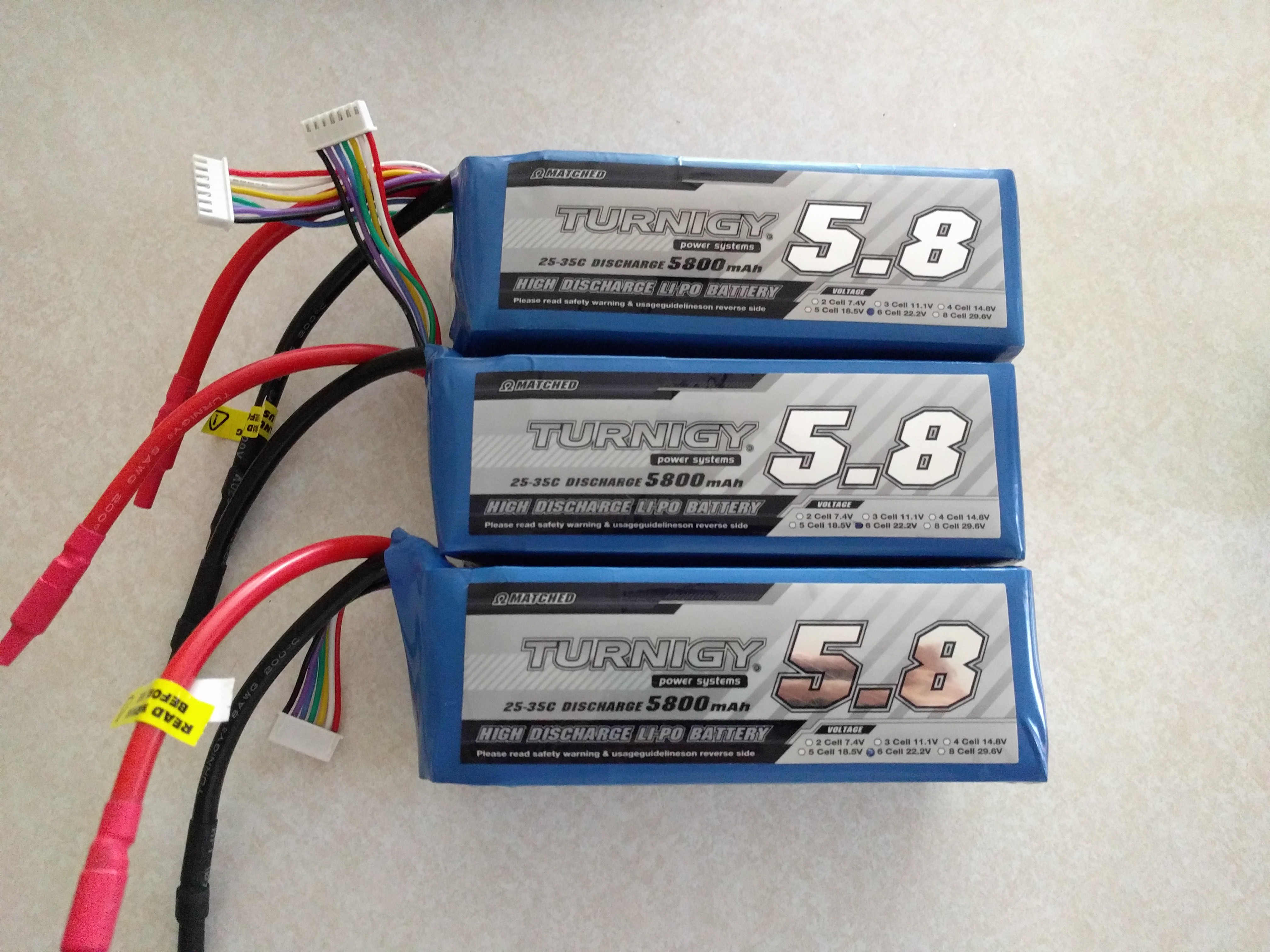
Decided to go with lithium polymer batteries, they are lightweight, have a high capacity, and insane discharge rate. The specs are: 18 cells in series, 66.6V, 5.8Ah, and 145A continuous discharge.
We also purchased the go kart frame around this time ( about a month into the project build)
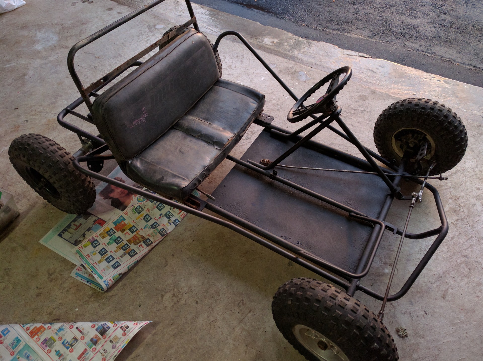 This is the rolling chassis that we purchased for about $125, it's in good condition except for the rotted seat and missing throttle pedal.
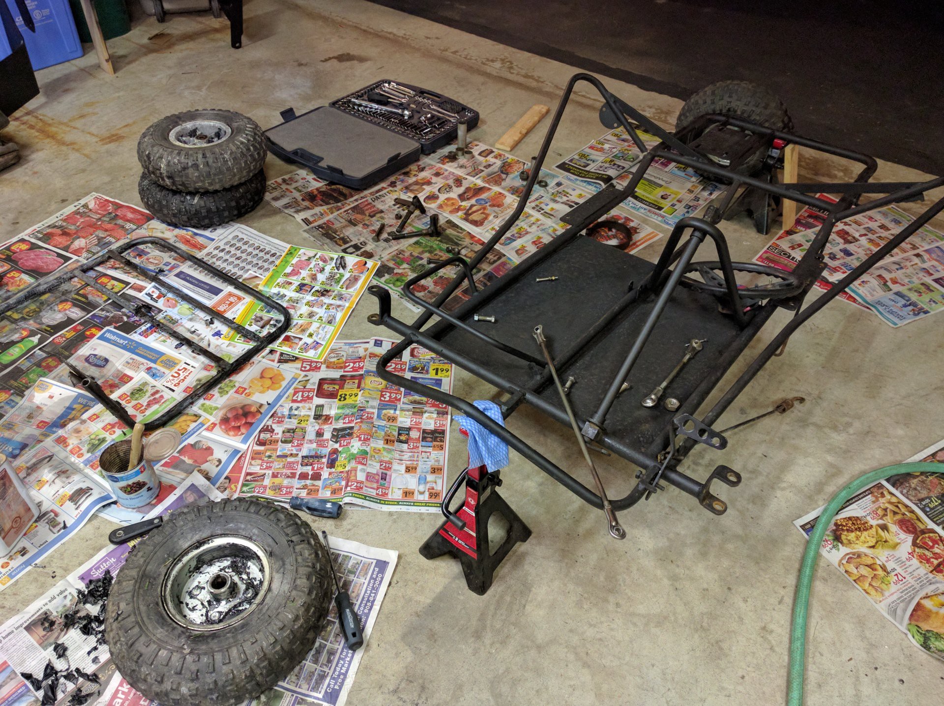
We took apart all of the rusted components and stripped the paint. Rust removing gel was used.
Next we needed to figure out a way of transferring power to the rear wheels. A chain drive seemed to be the simplest implementation.
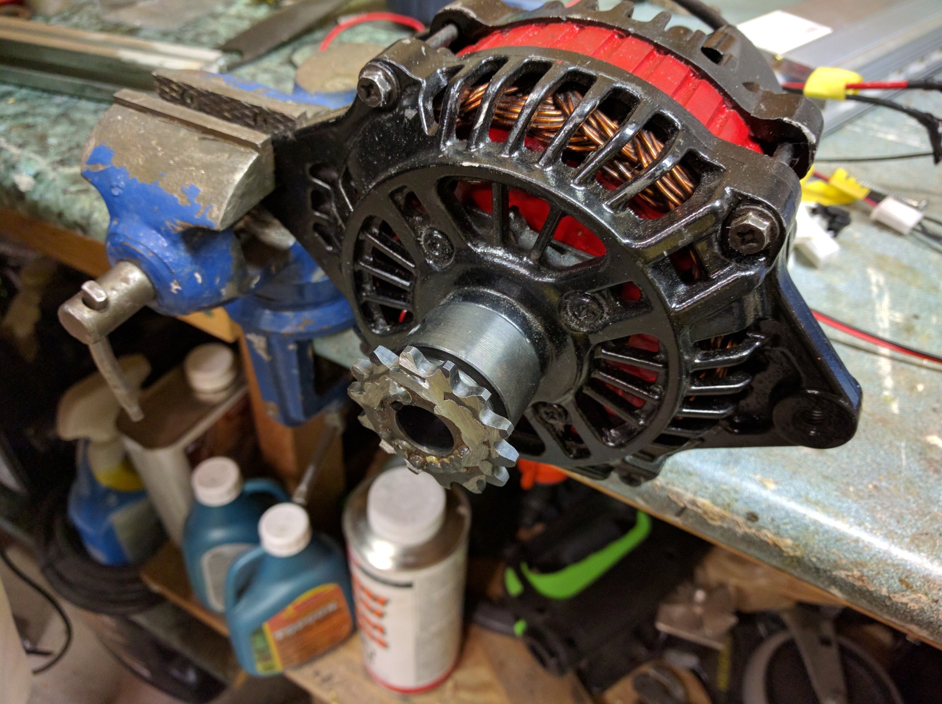
14 teeth #35 chain sprocket installed on the motor
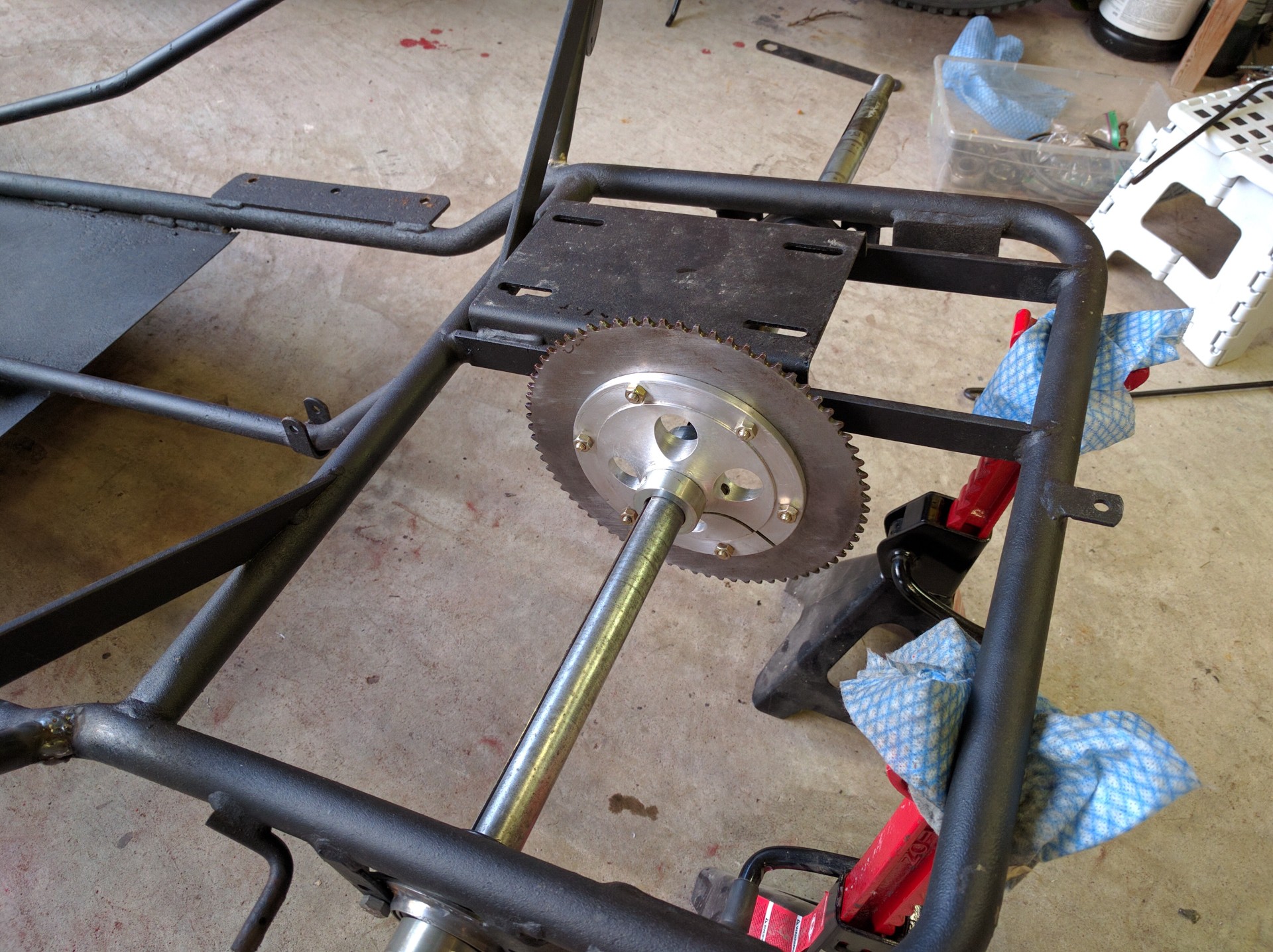
Drive sprocket installed on the live axle. This one has 72 teeth. This gives a gear ratio of 5.14 to 1
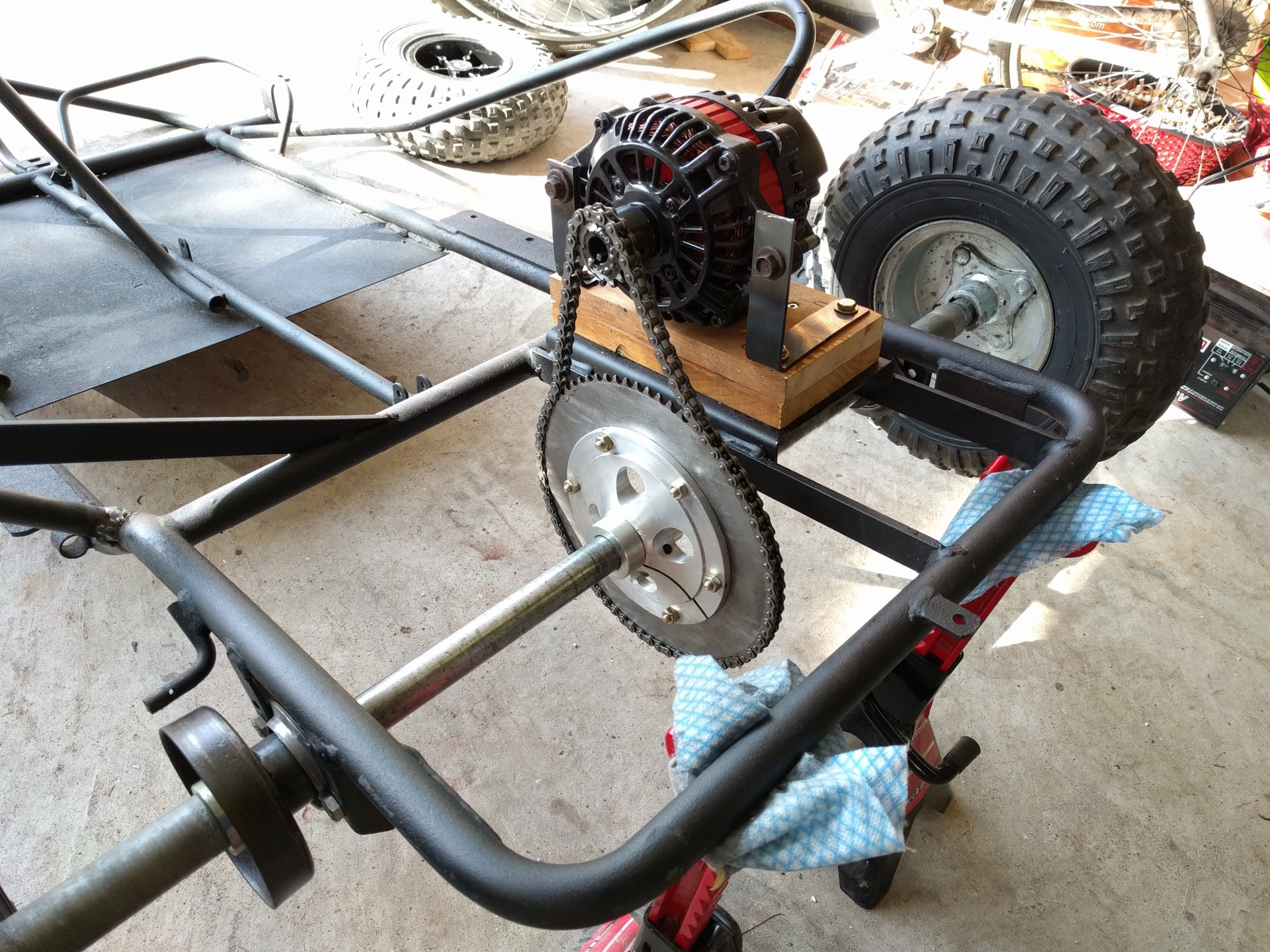
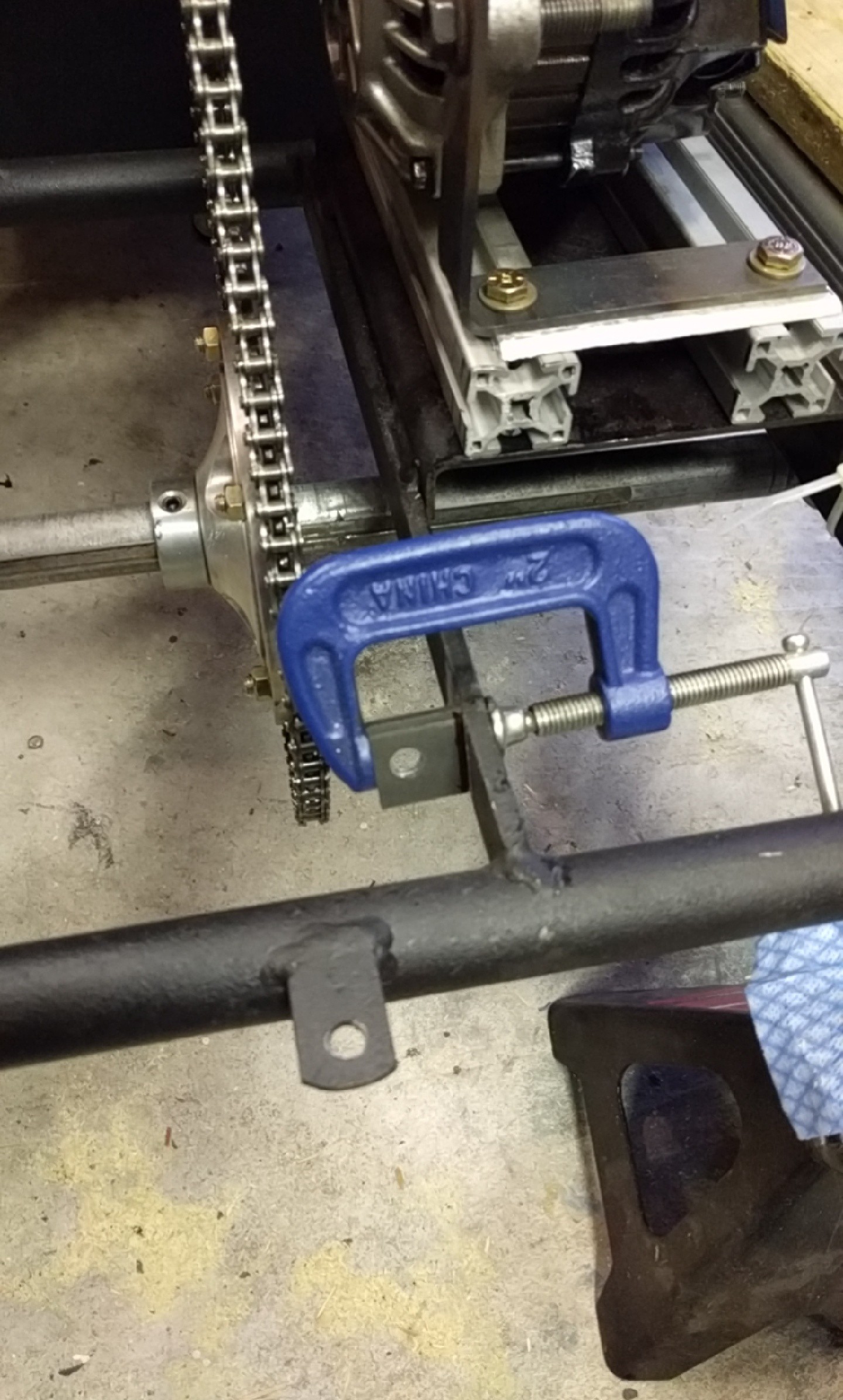
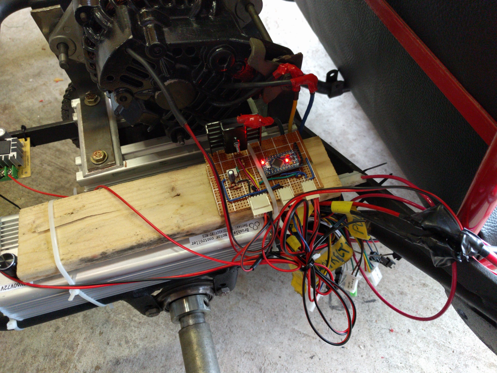
Motor installed on a temporary wood spacer, as well as the chain was test fitted. The wood spacer was later replaced by 2 aluminum beams.
Next we painted the wheels.
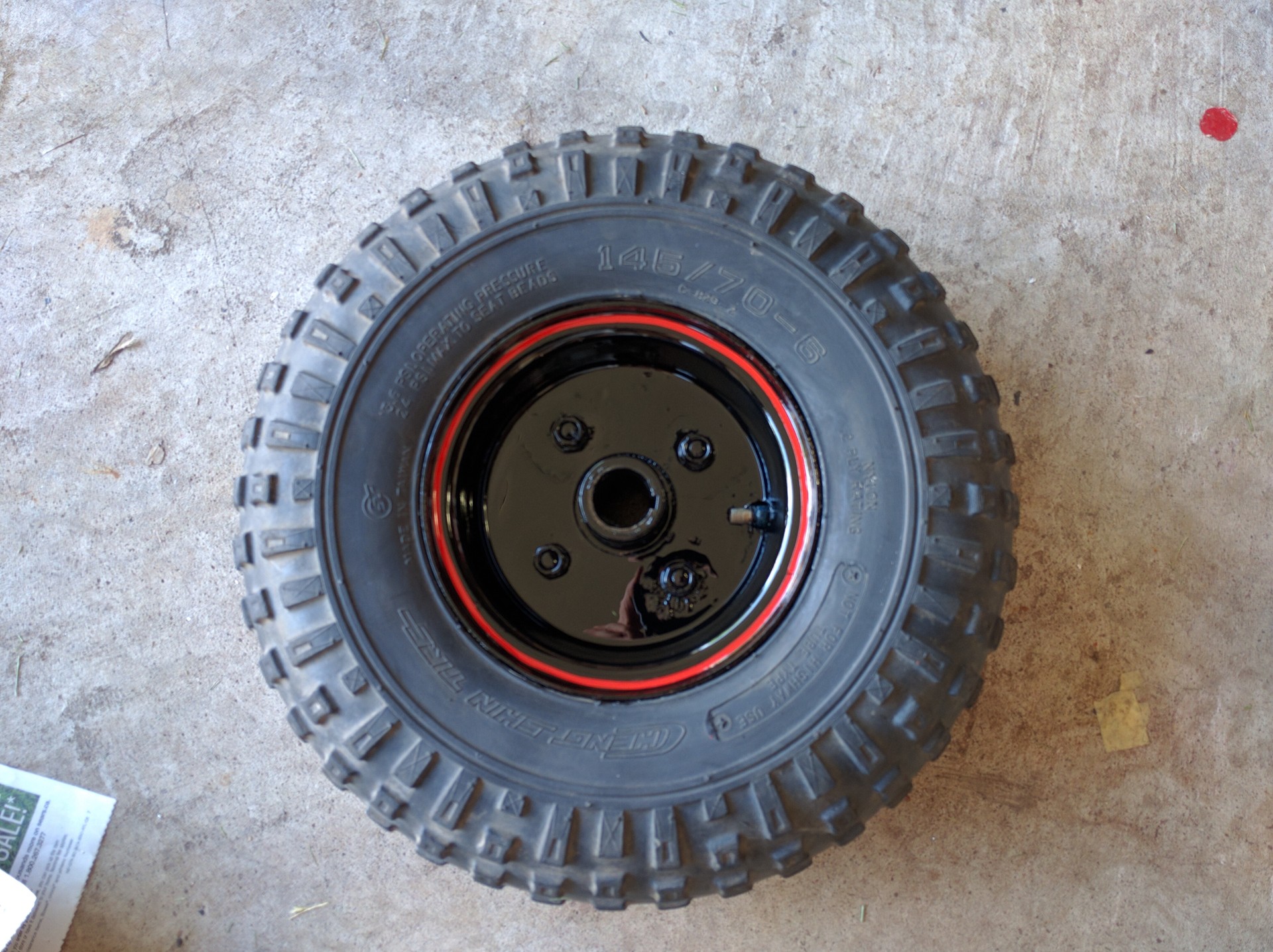
Glossy black with a red pinstripe.
Reupholstered the seat and painted the seat frame.
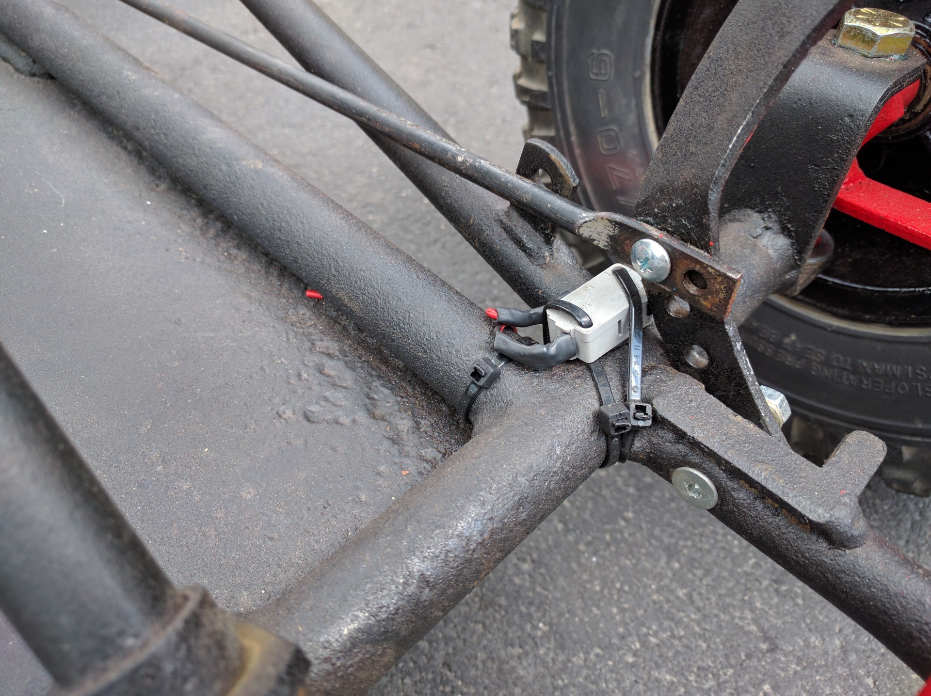
Testing the alignment of the sensor, the chain does not seem to affect the performance,
Here is a block diagram of the electrical system
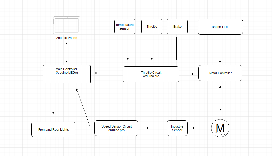
We are using an arduino pro mini for the controller interface circuit, another pro mini for the motor rpm measurement, and an arduino mega. We are using the arduino mega for its' serial ports.
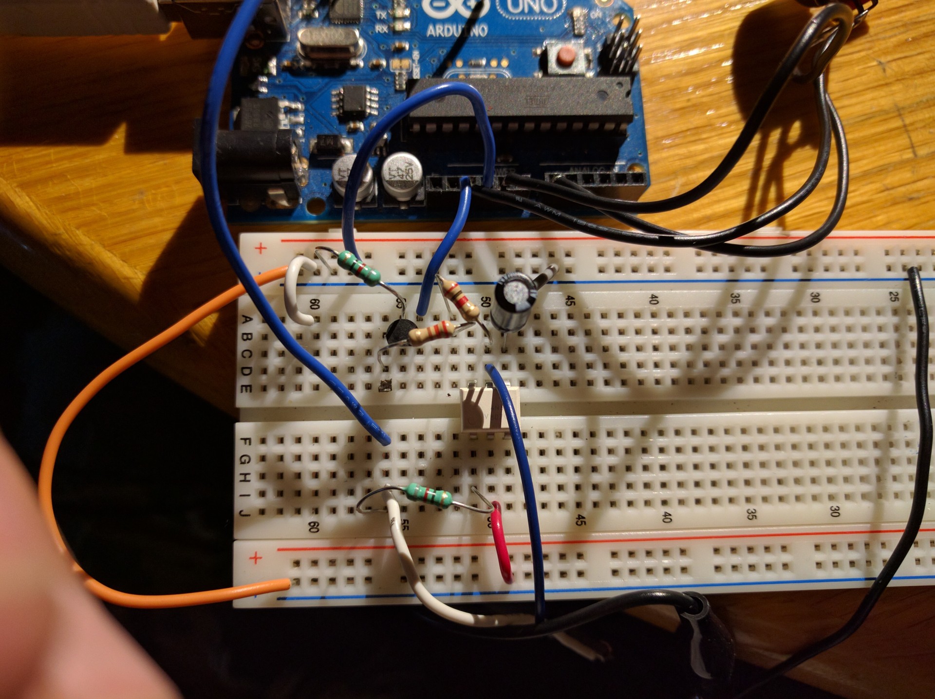
The throttle input on the motor controller expects a DC voltage between 1.1v and 4.1v, since the arduino does not have a DAC, we made a low pass filter, which converts the pwm square wave into variable DC. See the video below for a demonstration.
Testing the throttle control and field coil circuit. Here we are also testing the interrupt driven OS on the arduino pro. We are using output compare for the timing and state machine logic. The communication is over SCI using receive interrupts. We wrote the protocol for exchanging information over the serial port.
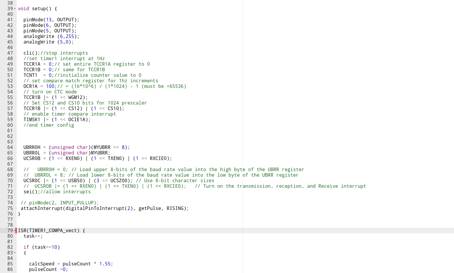
Code snippet showing the timer1 and sci setup.
Next we attempted to make a battery management pcb, in order to protect and charge the lithium polymer batteries.
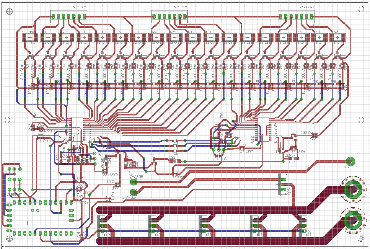
Here we are using the LTC6803-3 multi cell monitoring IC. each chip can handle a minimum of 4 cells and a maximum of 12. There are 2 cascaded in order to use 18 cells. An arduino pro mini provides the interface.
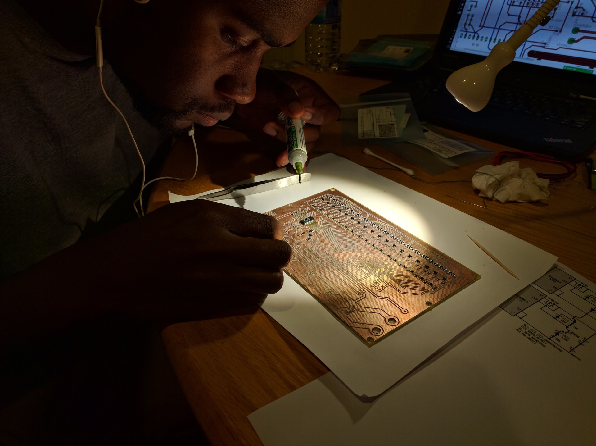
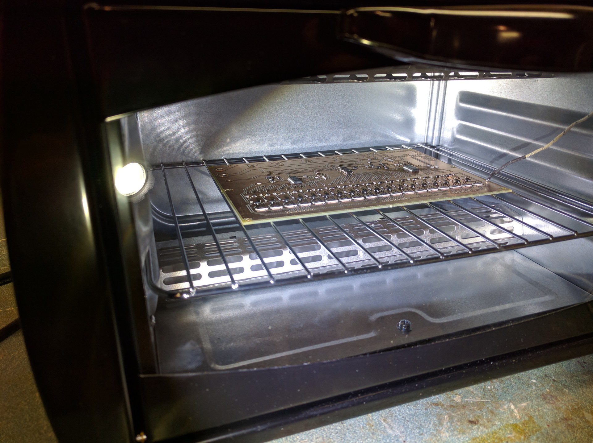
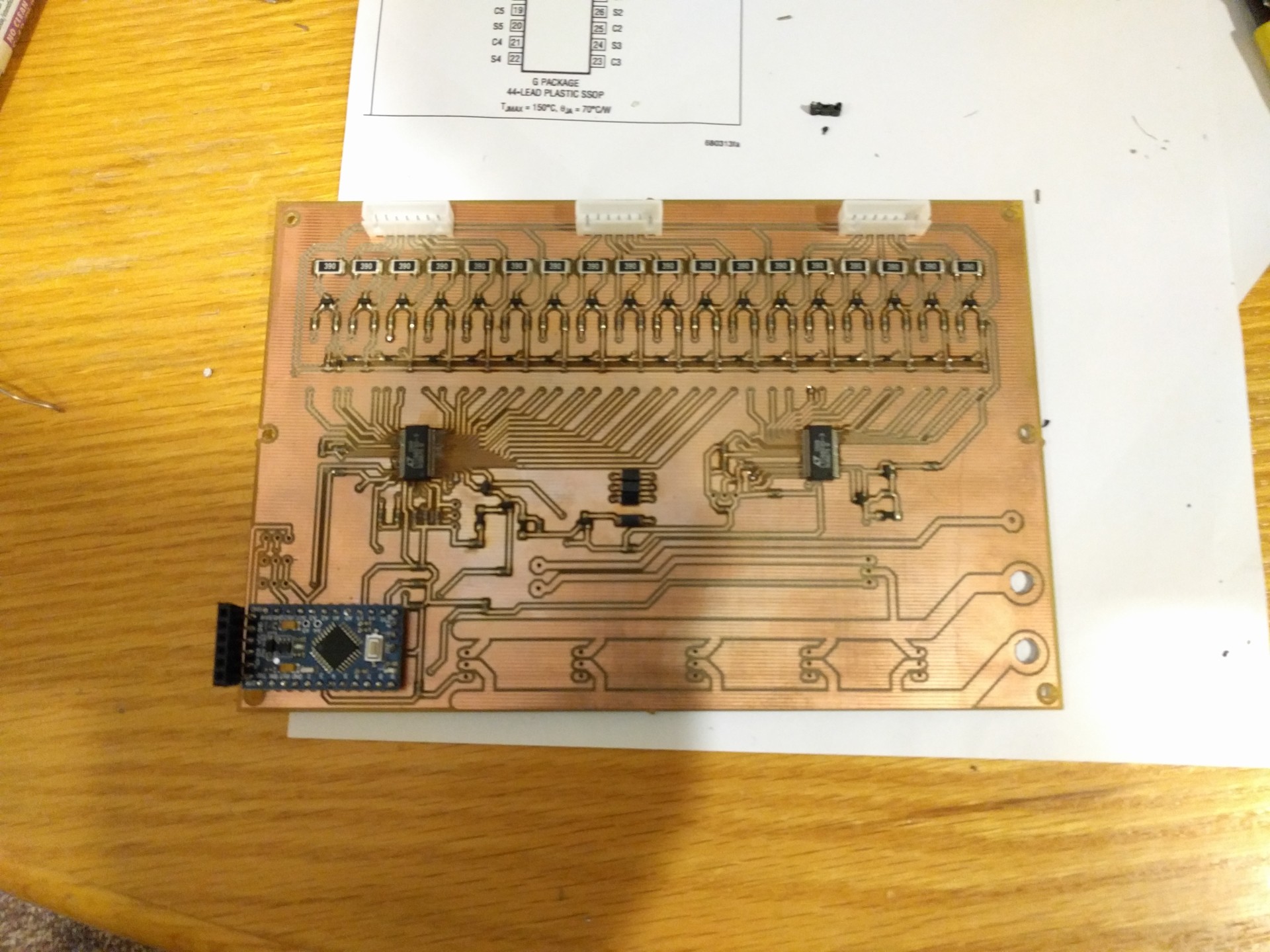 All done, minus the power mosfets. Unfortunately the IC on the left slightly shifted while it was in the oven. Some of the 44 connections are not reliable. :(

Meanwhile, we 3D printed a case for the arduino mega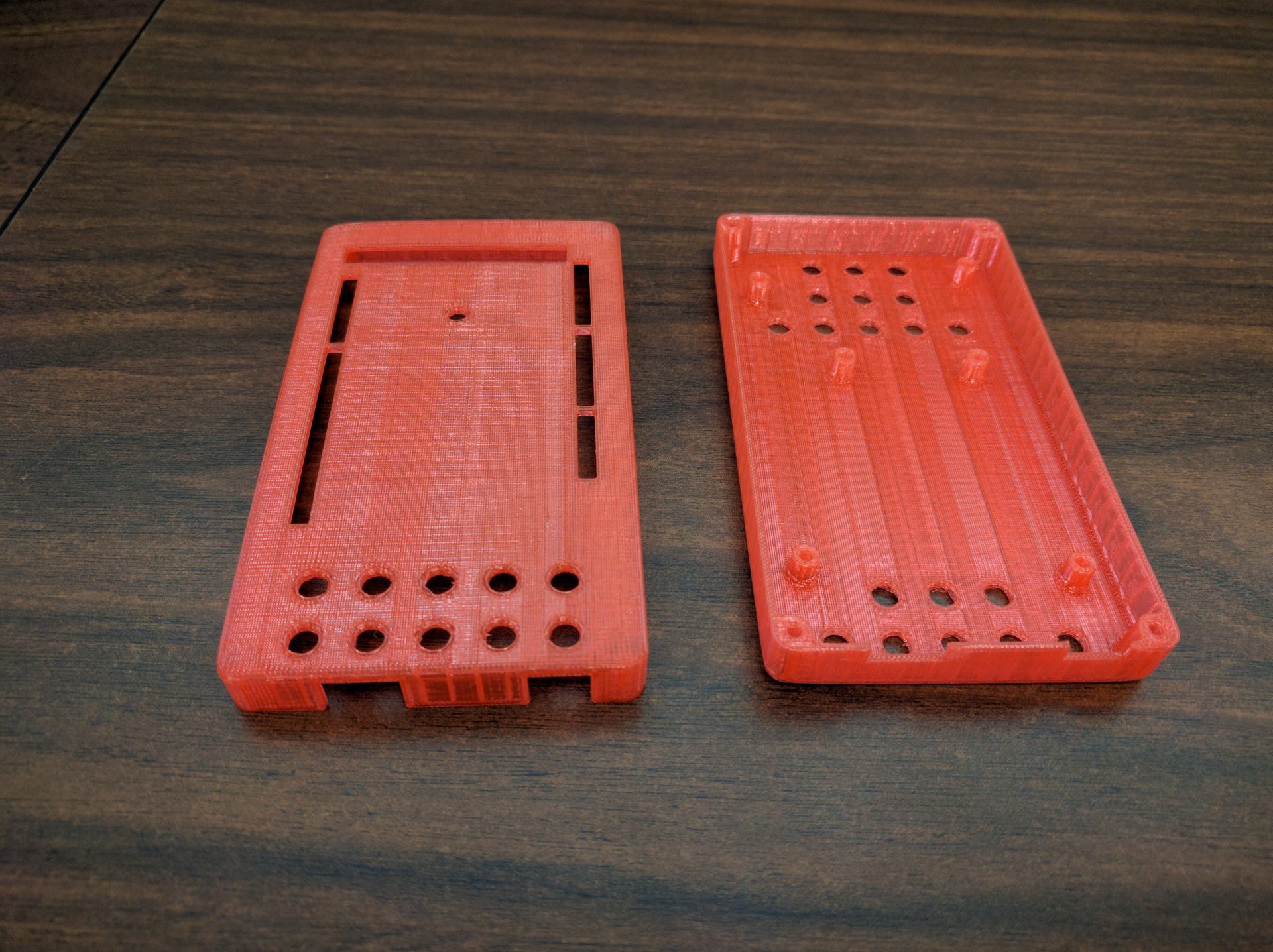
Fits well, but the screw holes are on the bottom ...
Purchased 1m of WS2812b led strip, for the front and rear lights
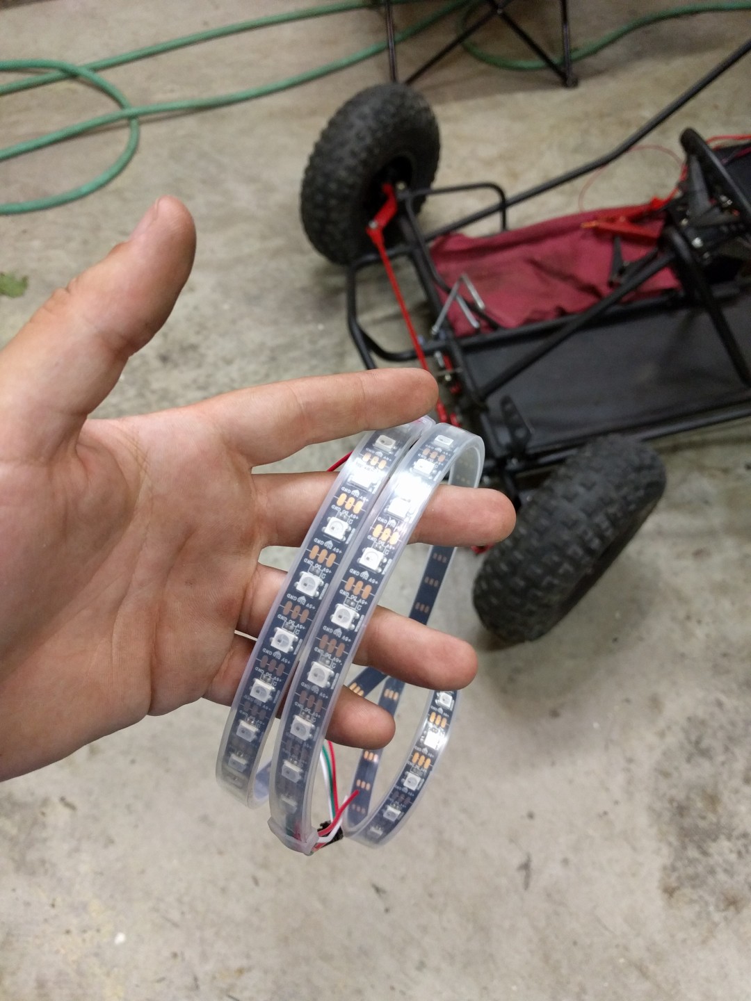 Used half for the front and the other half for the rear. In total there are 60 LEDs.
 Looking good!
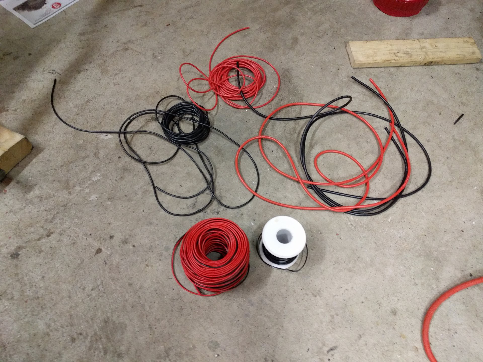 Now it was time to start the wiring. We used 12 awg silicone wire for the power connections, 18 awg for signaling and lower power connections.
Wiring took about 3 days.
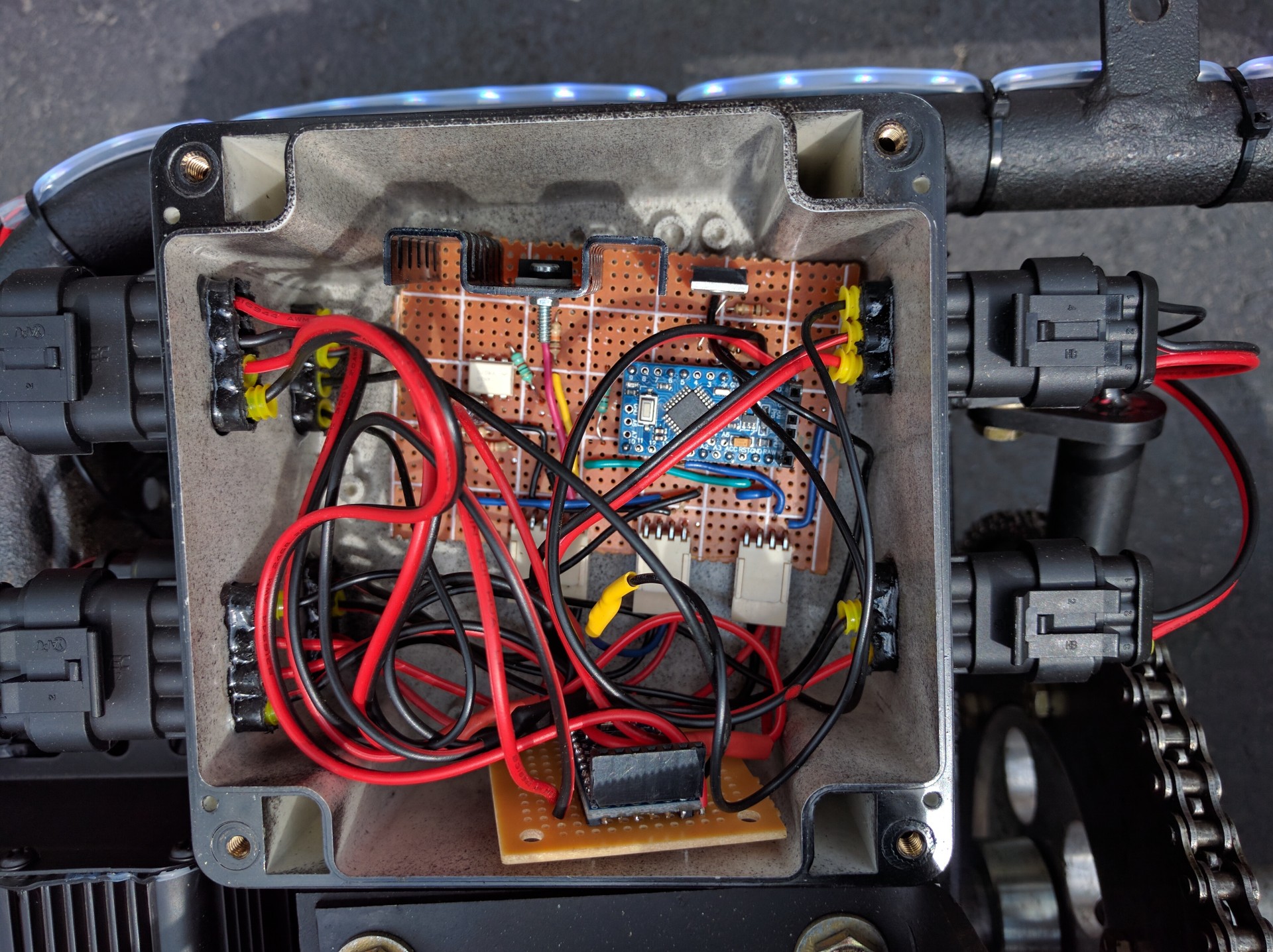
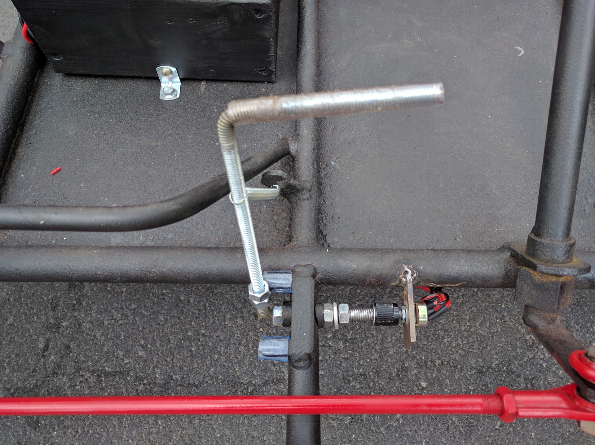
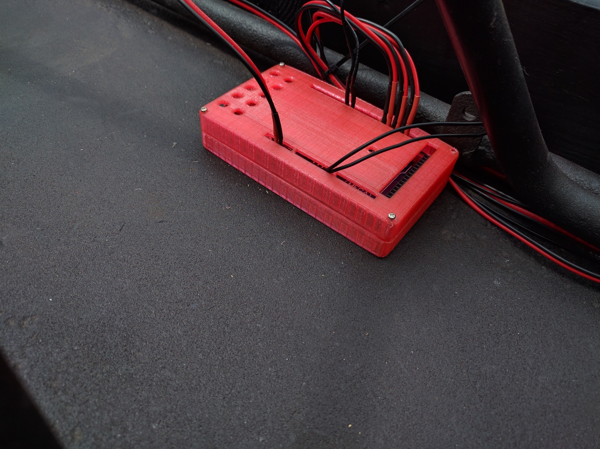
We made a box to house the throttle circuit and the speed sensor arduino pro mini.
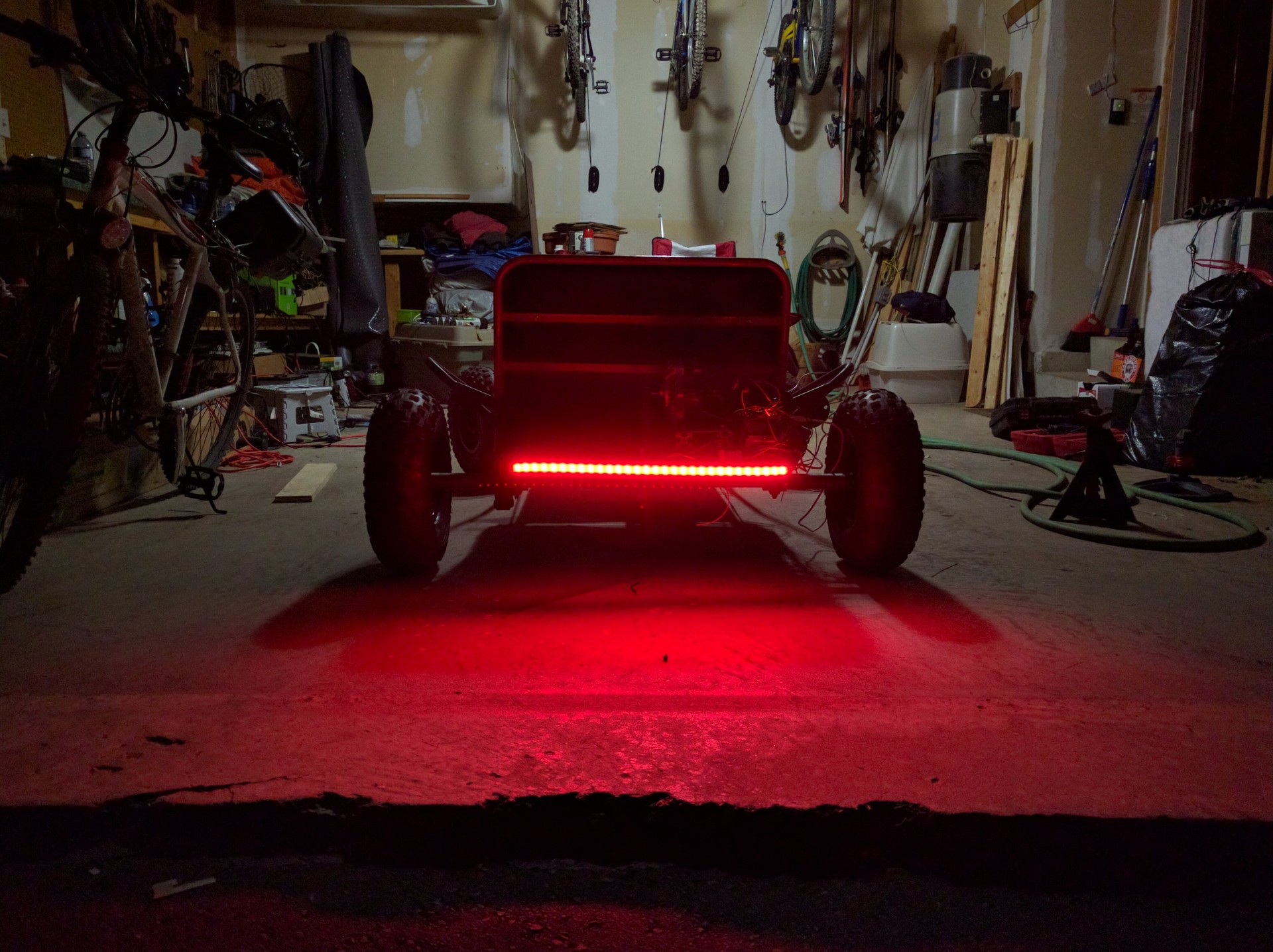
Rear lights are re-installed

Front lights installed
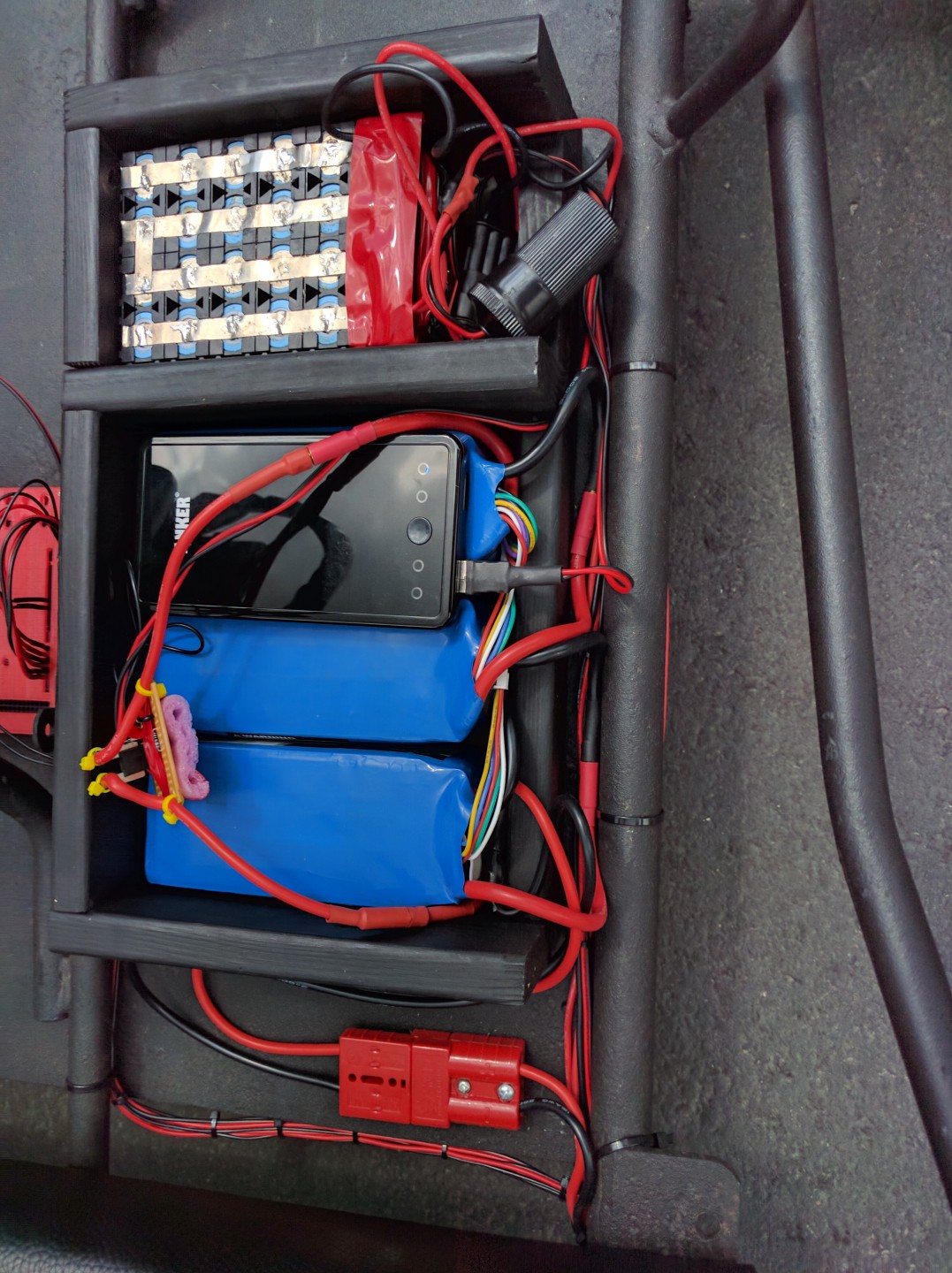
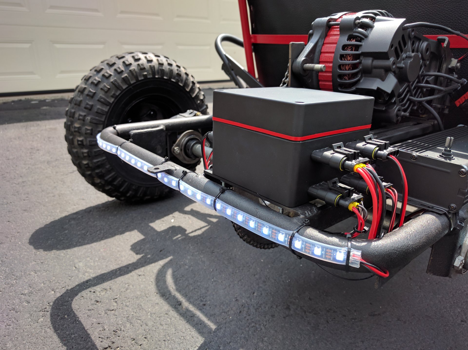
The battery box finished and installed. We were using a DC-DC converter to power the lights and arduinos, but it could not handle more than 1A, so we had to use a USB portable battery.
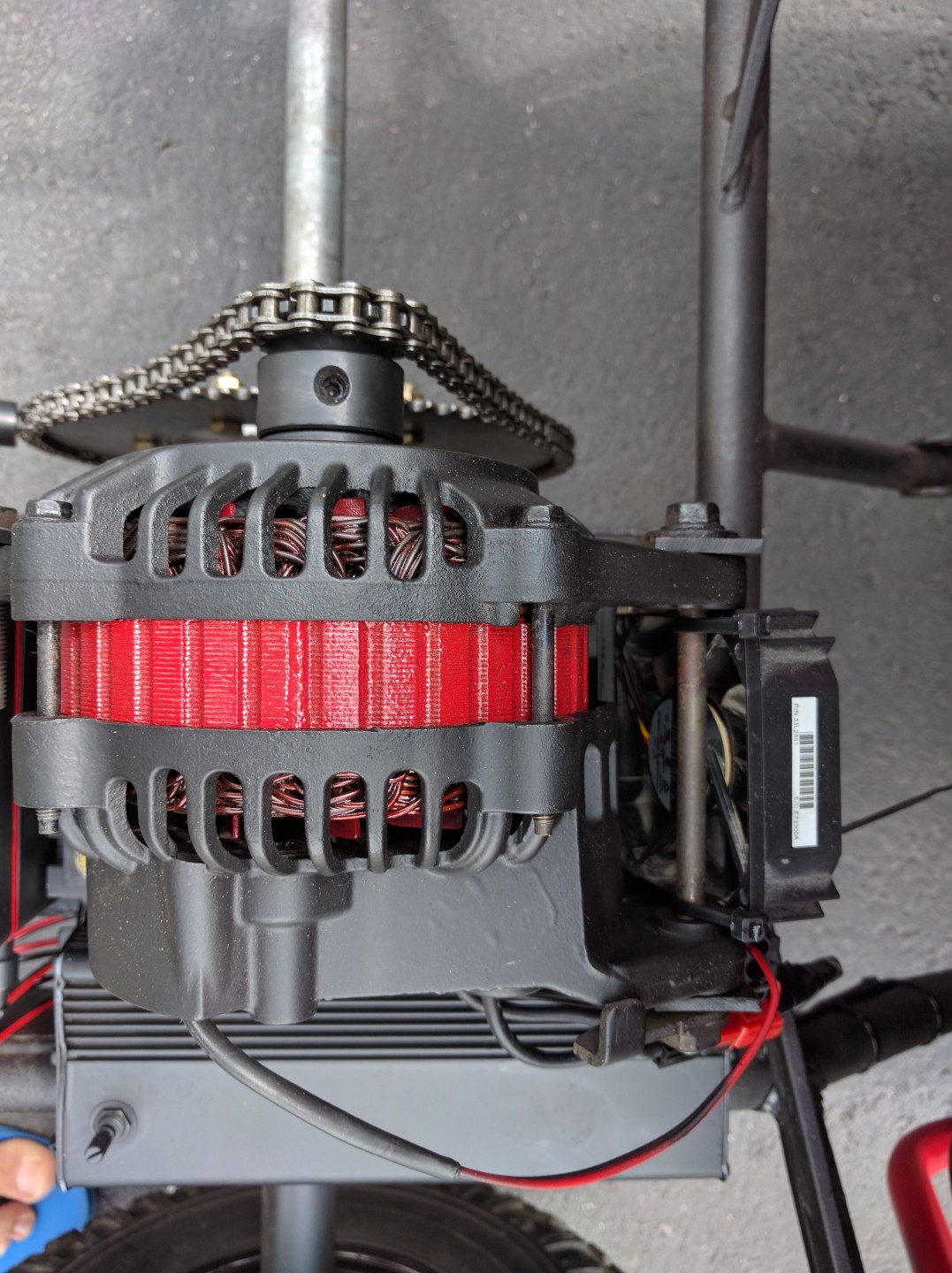
We added a cooling fan and temperature sensor (under the motor)
The final step was to make the android app.

We used Ionic framework, which allowed us to build an android app using web components. (Angular JS, and JQuery)
The app communicates over bluetooth with the arduino network.
Night Testing!
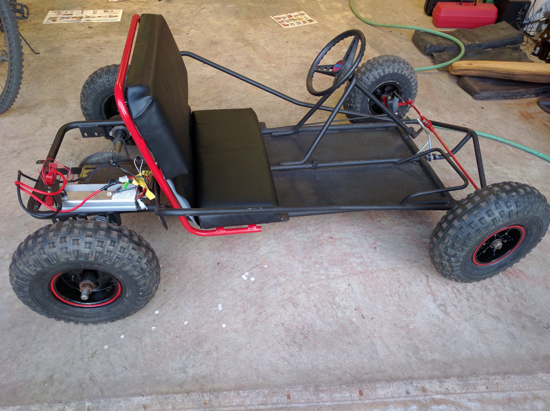
Finished E-Kart :)
Final Demo!
Top speed is about 53km/h
Total cost: ~$1500