 Krunal
This project is developed to control the speed of the three phase water pumping motor using VFD with respect to pressure
We have two solar parabolic reflectors installed at our premises as shown in the attached photo. We are using them for heating the water as well as for cooking for a group of 150-200 people.
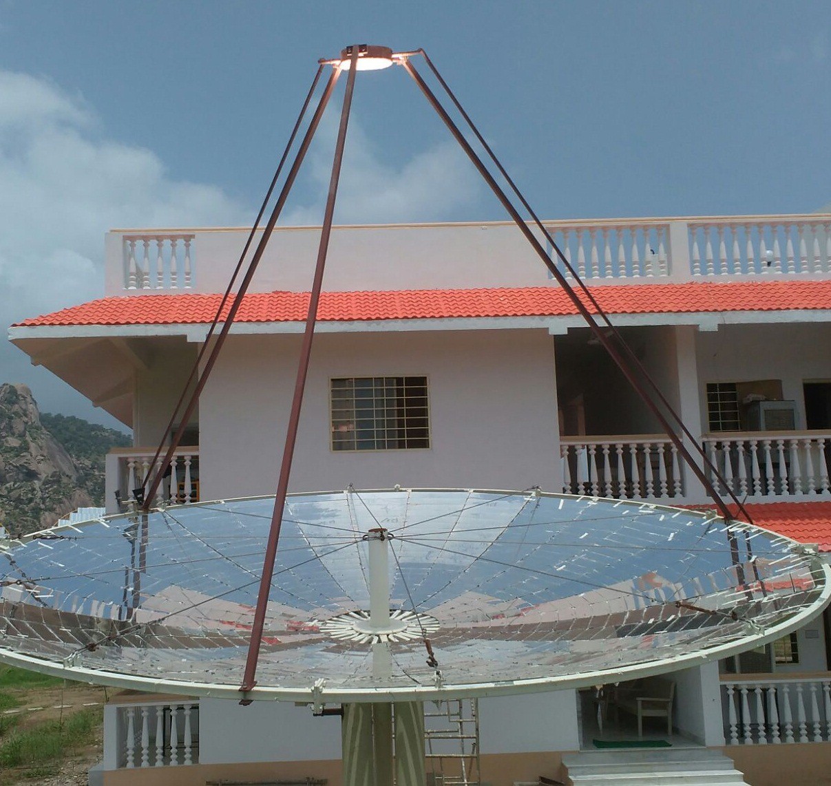
The solar reflectors are concentrating their energy in the form of heat on the metal receiver which gets heated up to 250° - 300° C. Then the water is pumped through these receivers using piston pump and motor. Due to the heat of the receiver, water gets heated and is converted into steam.
This steam is then taken to the steam accumulator, where we are storing the energy in pressurized accumulator so that it can be used for the whole day. The input pressure to this accumulator needs to be fixed at 5 BAR. This input pressure to the accumulator is dependent on the frequency of the motor as well as the usage of the steam from the accumulator. When the usage is more, the pressure drops and when the usage is less the pressure rises.
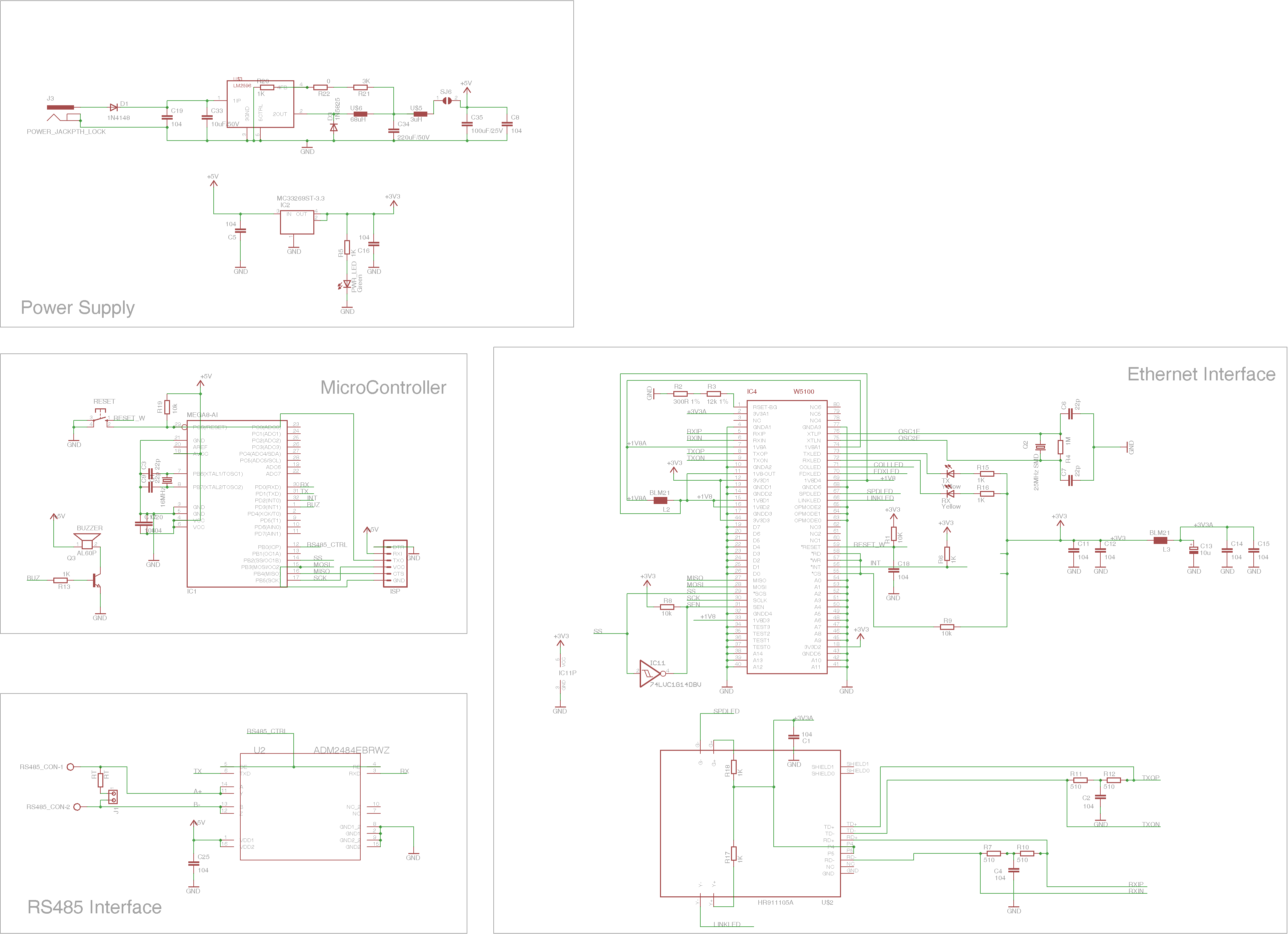
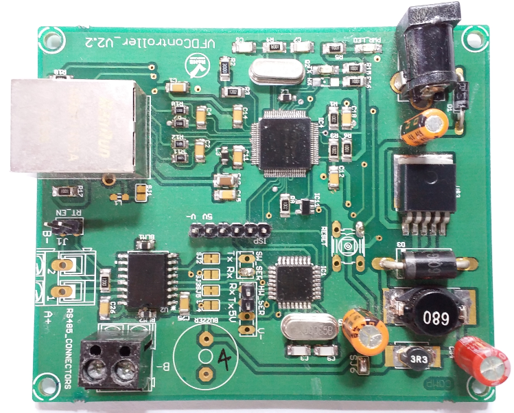
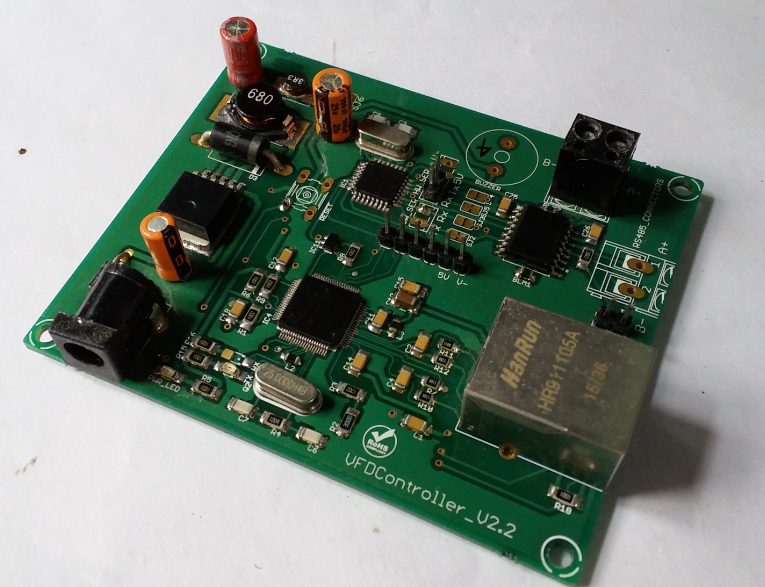
So to keep this pressure fixed at 5 BAR, a system is designed using Arduino and Ethernet shield, Let us call it Arduino VFD Controller.
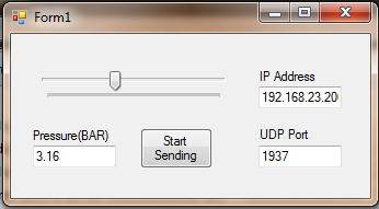
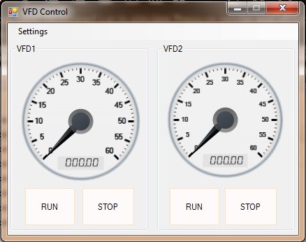
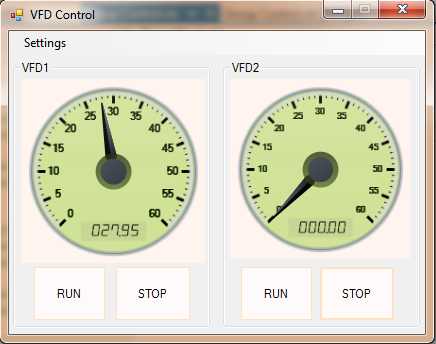
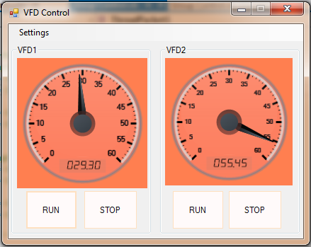
The system needs to monitor the pressure to the accumulator and accordingly vary the frequency of the motor using VFD. A Graphical User Interface(GUI) is also provided to the user to control the Motors as well as to monitor the frequency the VFD.
Two VFDs are needed for two dishes and a pressure sensor at the input of the accumulator. The Arduino VFD Controller is kept with VFD & three phase motor which are near dishes. The actual distance between the pressure accumulator and these solar dishes is too much and thus pressure sensor can not be connected directly to the Arduino. So one more system was designed just to read the pressure and send it to the Arduino VFD Controller. The communication between these two systems as well as communication to the GUI is implemented on ethernet layer using UDP protocol. Arduino Ethernet shiled with W5100 is used for this purpose.
To implement pressure regultor with arduino PID logic is implemented using PID library from...http://playground.arduino.cc/Code/PIDLibrary
One Arduino is going to control two VFDs. So two PID instances were created. According to the input pressure, the PID logic will calculate the output frequency separately for both the VFDs.
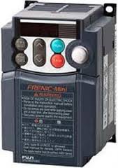
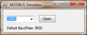
To control the frequency of the motor, the analog port of the VFDs could have been used. But it requires 0-10V signal level,which would have added another voltage regulator & a DAC with Arduino. The selected VFDs support MODBUS over RS485, So RS485 communication link is used to communicate between VFD and Arduino using MODBUS protocol. VFD is from FUJI drives with inbuit MODBUS protocol over RS485 communication link.
FUJI MAKE VFD part Number: FRN0007C2S-4A
Now the actual flow goes like:
- Arduino VFD Controller will get pressure on UDP port over ethernet from another pressure sender installed at accumulator...
- It will process using PID logic and will give two output frequency for two VFDs...
- These two output frequency will be then sent to the two VFDs using MODBUS protocol on RS485 link...
- VFDs will be driving at these new frequency...
- Meanwhile if user wants to monitor or control the VFDs run using GUI: GUI will be communicating with the Arduino VFD Controller using UDP protocol. Arduino will be sending this information to the GUI as well as will stop or run the motor as per commanded from the GUI...
Please see the "Instructions" section to learn how to simulate or to test the actual system.

 Adrian Georgescu
 igorfonseca83
 kurimawxx00
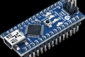
 ken.do