 Krunal
Three GUIs have been developed to test the code: The GUIs can be found here...
Two GUIs have been developed just to simulate Pressure sender and VFD to test the development...
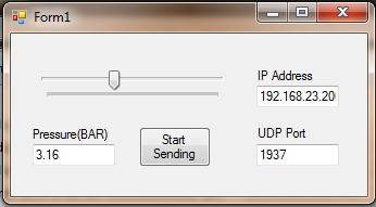
- Pressure Sender Simulator: This pressure sender PCB's work is in progress, so GUI simulation is used. It is acting as Pressure sender installed near accumulator. This GUI only send pressure to the Arduino VFD Controller. Pressure can be varied with track bar from 0 - 8 BAR in the step of 0.01 BAR. This GUI works on UDP protocol.
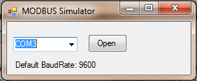
2. MODBUS Simulator: It is acting like VFD. Only Write one register of MODBUS fuction can be tested with this GUI. This GUI works on MODBUS protocol. This should be connected to the serial port of the Arduino VFD Controller while any other program using serial port of the Arduino should be closed before... (This is just test GUI and so I could not add all the MODBUS functions, however, all the codes are tested with actual VFD.)
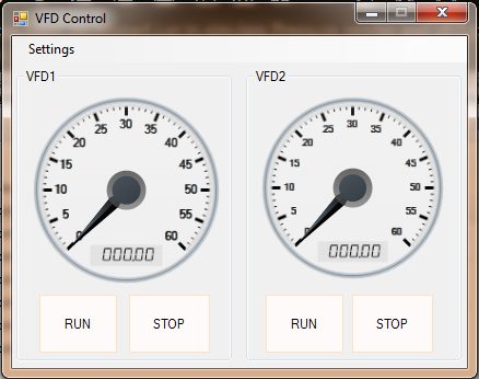
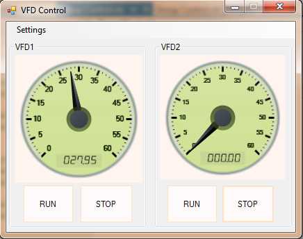
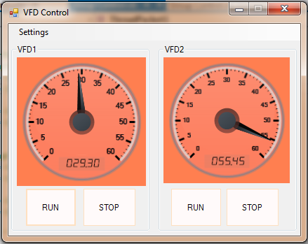
3. VFD Controller GUI shows the real time frequency of the both the motors, Also it shows the connection status of the VFDs. If any VFD is disconnected, it will show that in Red color else will be showing green in normal operation. User can even control each motor and can run/stop individual motor. We need to specify the IP address of the Arduino VFD controller to this GUI using settings tab(Default IP: 192.168.23.200). This GUI is not a functional requirement for the Arduino VFD Controller, but it is just for monitoring purpose.
When both VFDs are connected and RS485 communication proper, then GUI will be green showing the actual running frequency of the VFD.
When there is any problem or if the communication fails, the GUI turn RED indicating loss of communication or some problem.
Discussions
Become a Hackaday.io Member
Create an account to leave a comment. Already have an account? Log In.