 jaromir.sukuba
I tried to replicate #TritiLED of @Ted Yapo
How I did it
I suggested replacing the PIC12F508 with some newer, low-power MCU, but instead of suggesting only, I tried it for real.
At first I tried the original code with original PIC12F508 that happened to sit nearby - to have solid ground for comparison. Then I modded it.
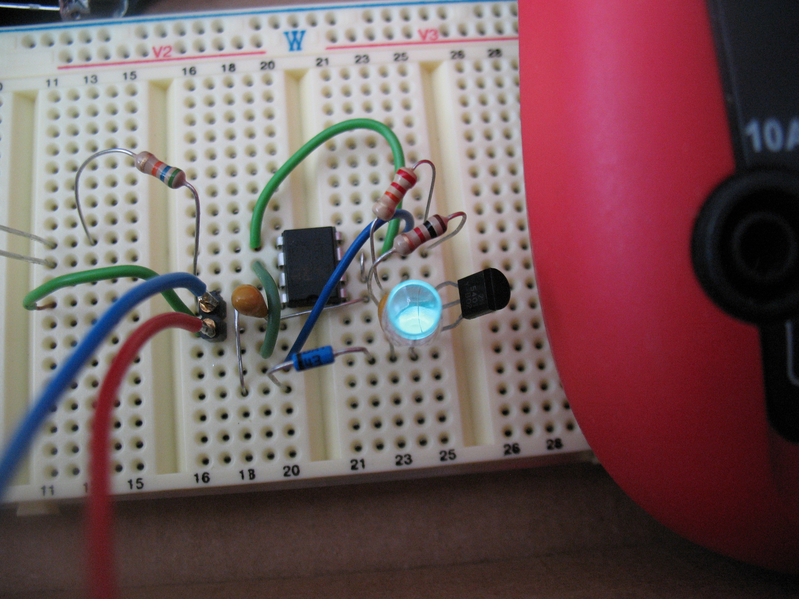
I used PIC12LF1552, because that's what I had on hand. Instead of ceramic caps I used 10uF/16V tantallum caps, diode is BAT48, transistor 2N5401 and LED is HLMP-CE13-35CDD, because that's what I had on hand. By the way, I bought the LEDs for a particular project two or three years ago and now it's obsolete - fortunately I used different LEDs for the final version of the project. It was built on a breadboard, 5-minute quick job.
The PIC12LF1552 is somehow different to PIC12F508, so I had to adjust the Ted's original code (by the way, missing <p12f508.inc> after #include keyword on 6th line, it assembler will throw error on original code) this way:
; tritiLED.asm : original version by Ted Yapo, for PIC12F508
; https://hackaday.io/project/11864-tritiled
; for PIC12LF1552 adjusted by Jaromir Sukuba
#include
 __CONFIG _CONFIG1, _FOSC_INTOSC & _WDTE_ON & _PWRTE_ON & _MCLRE_ON & _CP_OFF & _BOREN_OFF & _CLKOUTEN_OFF
 __CONFIG _CONFIG2, _WRT_OFF & _STVREN_ON & _BORV_LO & _LPBOR_OFF & _LVP_ON
	ORG     0
	movlb	0x01		; bank 1, where interesting registers are
	movlw	0x60
	movwf	OSCCON		; set up to 2MHz
	movlw	0x08
	movwf	TRISA		; set up input-output pins
	movwf	WDTCON		; fallthrough to WDTCON, set 16ms WDT
        movlw	LOW LATA	; get LATA adress
	movwf	FSR0L		; move to FSR0, use it as reference
	movlw	HIGH LATA	; so I can avoid touching BSR again
	movwf	FSR0H		; and high byte of address too
	movlw	b'110110'	; GP1/2/4/5 H, GP0 L
	movwf	INDF0		; this is now actually LATA
MAIN_LOOP:
	comf	INDF0		; GP1/2/4/5 L, GP0 H -> discharge
;	nop			;
;	nop			; optional NOPs, wider pulse, more current
	comf	INDF0		; GP1/2/4/5 H, GP0 L, sleeping, charging a cap
	sleep			; sleep for 16ms
HF_NR:
	btfss	OSCSTAT,0	; after waking up by WDT
	bra	HF_NR		; wait for oscillator to get ready
	bra	MAIN_LOOP	; and do another blink
	END
In fact, there is not much of original code left, but the idea is still the same.Because PIC12LF1552 WDT doesn't allow 18ms, I set it to nearest value - 16ms.
How it performs
It works. With original Ted's circuit the 3us wide pulse and 18ms sleep time circuit draws 15uA (approximately half of the current draw measured by Ted - probably beacuse of different LED). With 2us impulse I got 11uA consumption at 3V, while light output was something I call OK-ish for night indication light. With PIC12LF1552 and 2us pulse I got approximately 1uA less current draw and the same light output.
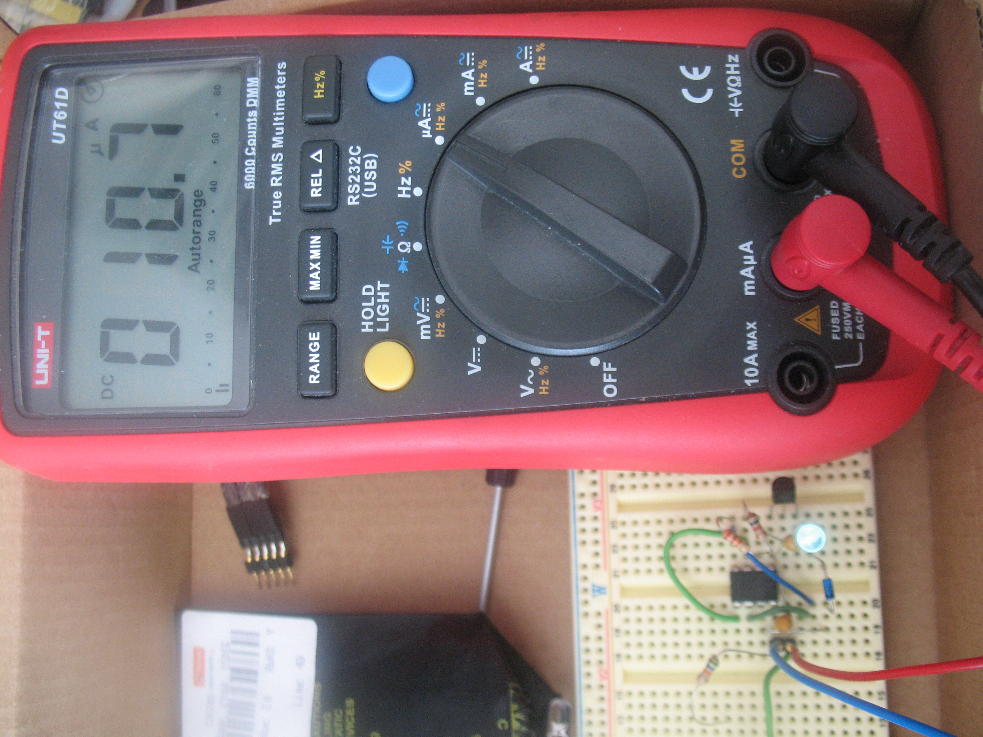
I breadboarded another LED next to the circuit, powered by DC current and tuned until the brigthness looked more-less the same.
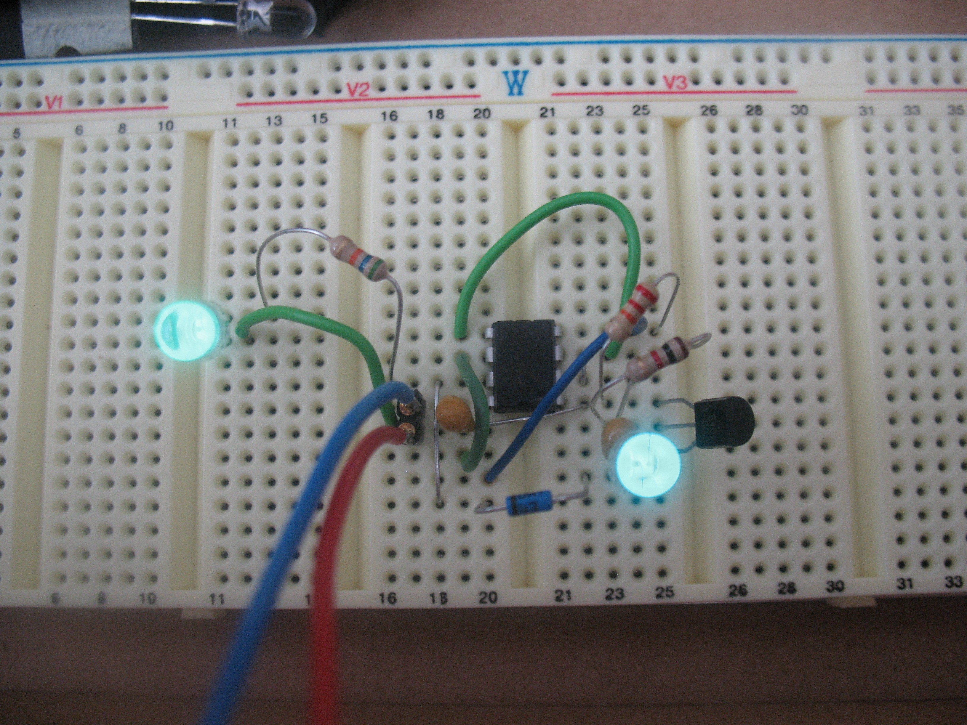
The DC powered LED has more green-ish output (higher wavelength, perhaps not very apparent on the picture) and draws only slightly more than total draw of pulsed circuit - 12,5uA versus 10,7uA. Ted's original circuit exhibited greater difference. Perhaps my LED isn't as efficient at high pulsed currents.
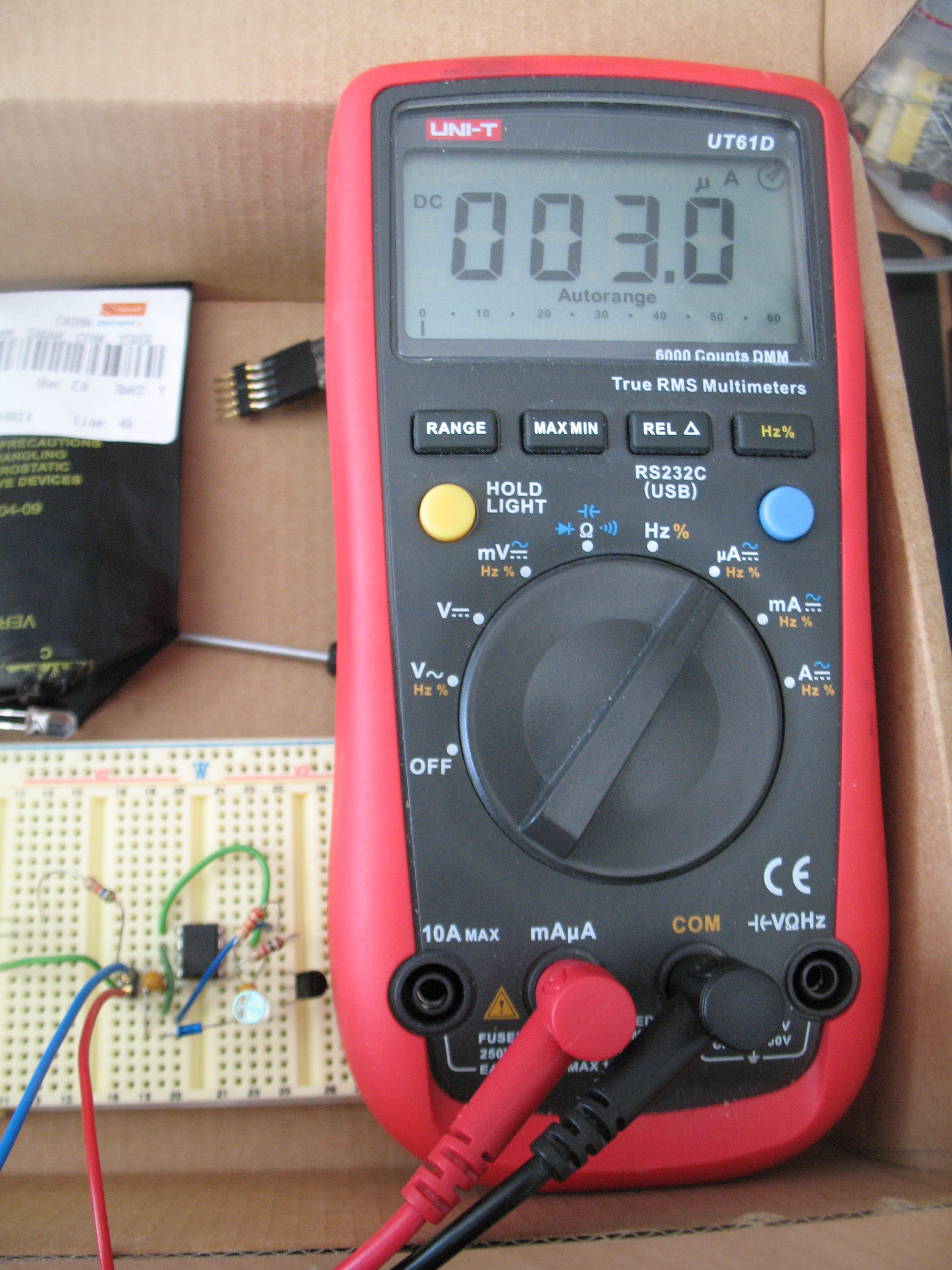
I decreased power supply voltage to 1,8V and it still performed well, with acceptable light for the purpose; DC powered LED produced no visible output. Interesting it drew only 3uA at 1,8V.
What to do now
I'll try to get some better LEDs and will see.
Discussions
Become a Hackaday.io Member
Create an account to leave a comment. Already have an account? Log In.
Actually, the wavelength shift is shown in figure 4 of the datasheet:
http://www.farnell.com/datasheets/1038179.pdf?_ga=1.226417875.893016060.1443690519
very thorough datasheet!
Are you sure? yes | no
Nice work! A few thoughts come to mind:
Thanks for the note about the missing #include - yours is missing, too :-) The editor here must not escape the angle-brackets, and it gets discarded as an improper HTML tag. You can fix it by inserting escaped brackets manually in the html-view of the editor.
I see the wavelength shift also - you don't see it discussed much, but it's apparently a known phenomenon, especially for green and blue LEDs:
http://www.lrc.rpi.edu/programs/solidstate/cr_effectsofdimming.asp
I'm impressed with the "modern" PIC results! It sounds like your original analysis was on-track. I'm going to have to try one of them...
I see in the datasheet (figure 3) for your LED that efficiency really does start to drop off at higher currents. They don't plot into the uA range, though.
The other thing is that the current pulse is "regulated" by the parasitics and other properties of the components. I don't have any 2N5401's around to try, but from the datasheet, it looks like they have lower beta and higher Vce(sat) than the 2N4401 or (expensive) ZTX718 I have been using. It might make a difference here.
One thing that might be possible is to simulate a larger-area LED die with paralleled T 1-3/4 LEDs in this circuit. With uW power levels, thermal runaway is not going to be a problem. I wonder if the Vf spread on the LEDs is tight enough to get away with it? You could hand-select a few matched ones, too.
11uA from a 225 mAh CR2032 battery will last 2.3 years, by the way. That's impressive!
Thanks for replicating the "experiment"! Now I have to order some newer PICs...
Are you sure? yes | no
Oh, wait. Maybe I read it wrong the first time through (before my first cup of coffee). The newer PIC draws 10% less current than the 12F508 for the 2us pulses. Less than I first thought, but still worthwhile.
Are you sure? yes | no
The much lower current draw (your 30uA vs mine 10uA) is IMHO mainly because of the LED and different timing - PIC has only small influence here. My LED has higher dynamic resistance at higher currents, probably. I can't compare the light output of your LED - maybe it is much stronger than mine, and if you would "underclock" you timing to get 10uA consumption, you'd get more light - I don't know.
So if you are going to replace the MCU, don't expect more than the two microamps saving. There is no microcontroller in the world that could bring you considerably more power savings here.
No matter what, I found the circuit with my timing and my LED at 10uA perfectly OK for the purpose.
I was aware of lower efficiency at high impulse currents, so my knee-jerk reaction was to put more LED in parallel - to divide the current and move the LEDs into more suitable conditions. It SEEMED like it produced more light output overall, but it is hard to measure by bare eye and I don't have any way to measure it objectively - perhaps just photodiode in current mode with integration sphere would do the job? I tried to take a photo of it, but narrow viewing angle of the LEDs in breadboard rendered photo unusable.
I'm going to buy some LED more suitable for this task, as well as changing the capacitors for ceramic type. I thought of using PMOS instead of BJT - what is your opinion on this?
Are you sure? yes | no
PMOS is a good idea - as long as you get one with a low-enough Vgs threshold (like maybe a 1.2 or 1.8V "logic-level" mosfet). I bought some to try in this application at one point - let me dig around and find them to see what I chose - too many boxes of parts around here :-)
I did some calculations comparing the Rds voltage drop for small MOSFETS vs the Vce(sat) for bipolars at one point, and I seem to remember it was a pretty close comparison for parts of about the same cost. If you're willing to spend more on MOSFETS, you can beat BJTs here.
I also dug through my LED box and found some HLMP-CE34-Y1CDD LEDs (on the same datasheet you linked). I think they're the same part you used, just from a lower-output binning (looks like 1/3 the output of the ones you used, unfortunately). Anyway, we can almost compare apples-to-apples.
Yes, the timing precision with a faster clock is nice to have available. One of the things I wanted to do was measure the battery voltage with an on-board ADC and adjust the timing to maintain an approximately uniform brightness as the battery ages. With the 12F508, there's no ADC, and you don't have fine-grained control over pulse width.
Are you sure? yes | no
Here are the MOSFETS I selected (and have in a box) for experiments:
n-channel:
https://www.digikey.com/product-search/en?keywords=zxmn3b01fct-nd
p-channel:
https://www.digikey.com/product-search/en?keywords=ntr1p02lt3gosct-nd
both in a package:
https://www.digikey.com/product-search/en?keywords=tt8m3ct-nd
I was thinking of replacing both the low and high side drivers with MOSFETS, then adding an inductor and free-wheeling diode to make it a hybrid switched-capacitor and inductor single-pulse converter. I'll draw up a diagram and post it on #TritiLED. I have a version of it breadboarded already, but it needs tweaking.
Are you sure? yes | no
Measured results at different MCU and sleep/pulse ratios.
PIC12F508 @ 18ms/3us - 15,7uA
PIC12F508 @ 18ms/2us - 12,2uA
PIC12LF1552 @ 16ms/3us - 14,4uA
PIC12LF1552 @ 16ms/2us - 10,7uA
Take the measurements with grain of salt, measuring sub-microamps on breadboard may be somehow misleading - but I think the difference is clearly to see.
Are you sure? yes | no
The #TritiLED project is still in my head, I'll might make one myself. Thank you for sharing :)
Are you sure? yes | no