0%
0%
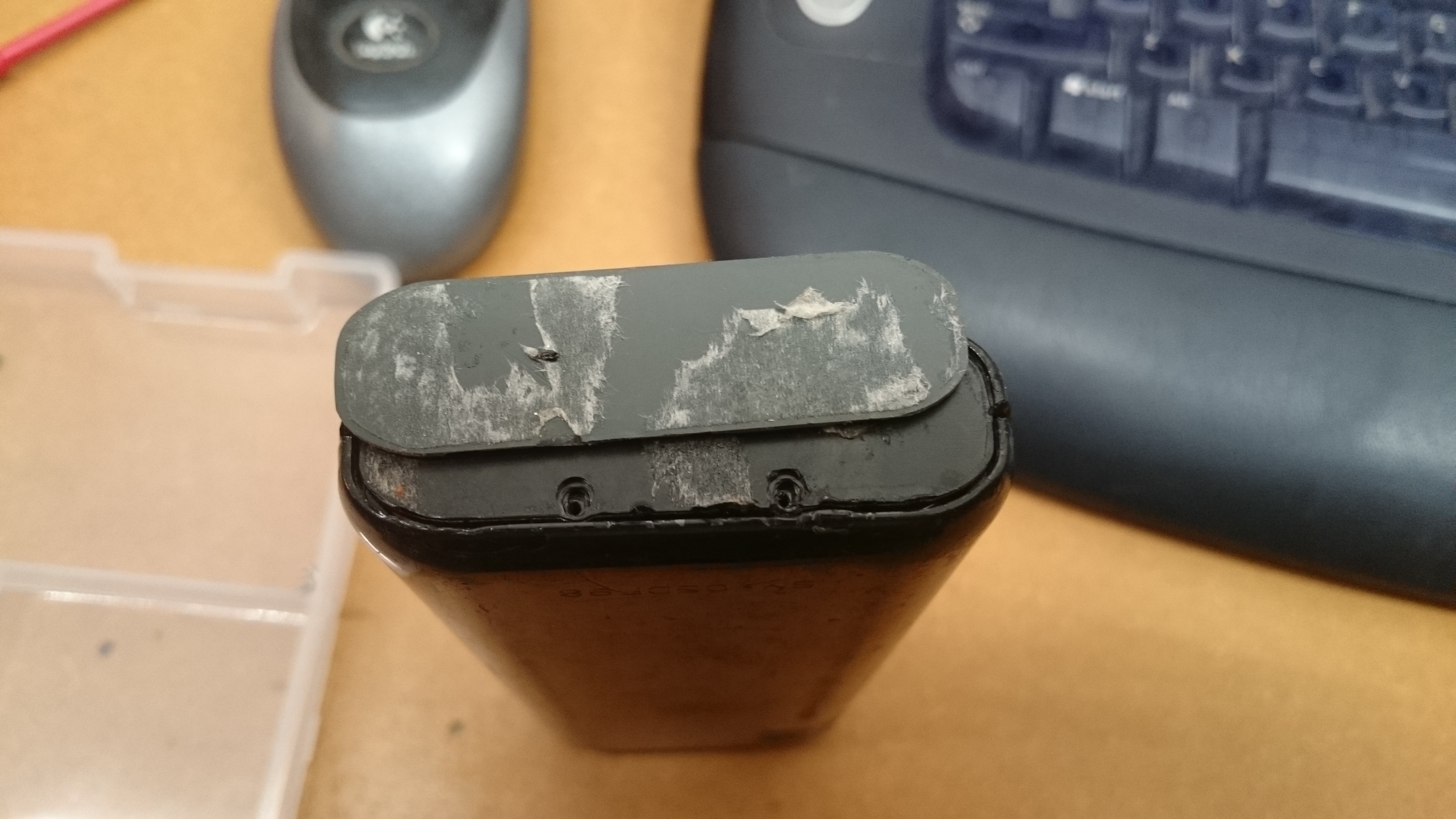
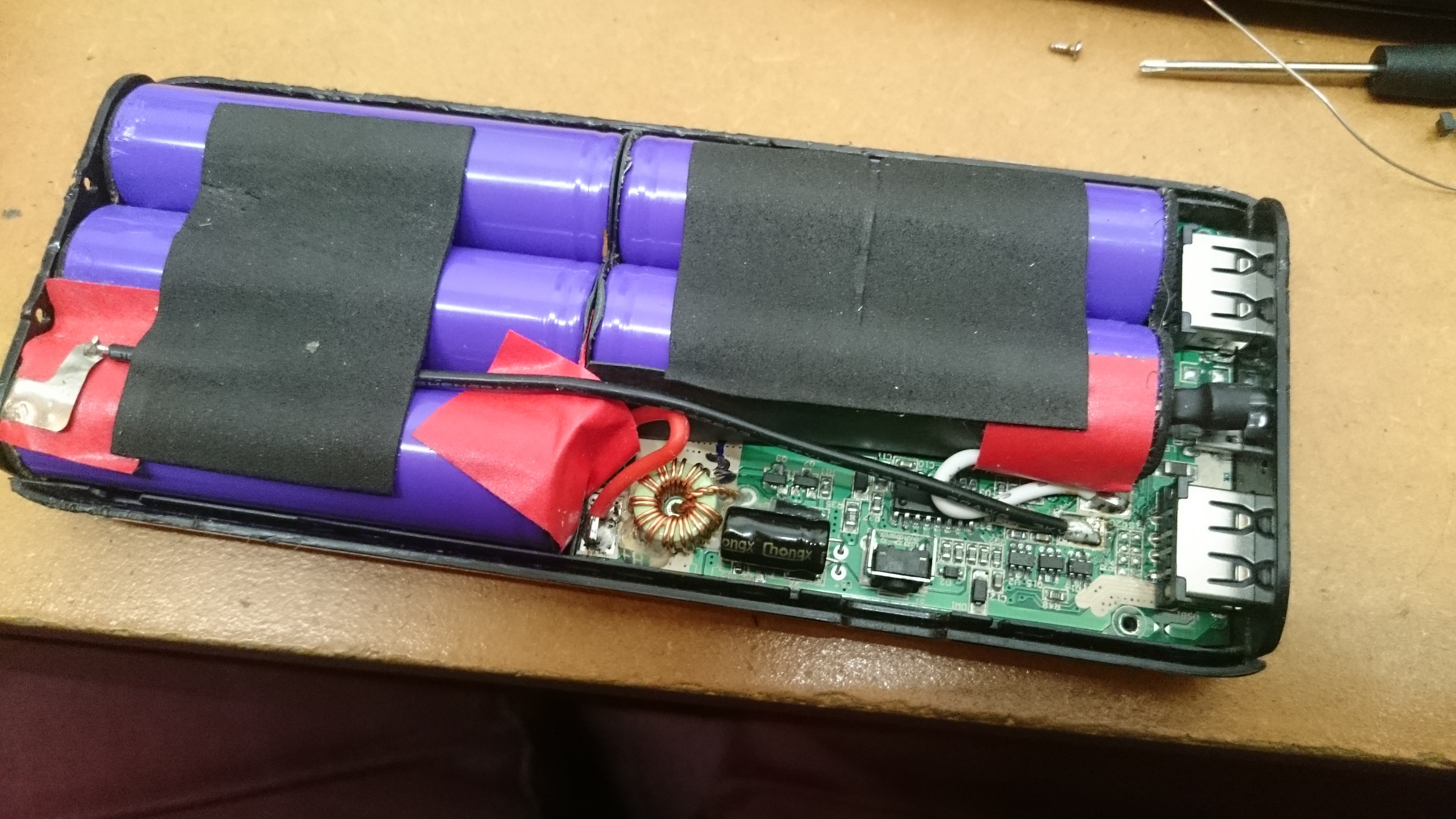
Repairing an Anker E5 16000mAh Powerbank
How to replace the USB connectors and/or ferrite bead on your Anker pack.
 ClimbinElectronics
Become a Hackaday.io member
Already have an account? Log in.
Just one more thing
To make the experience fit your profile, pick a username and tell us what interests you.
Pick an awesome username
hackaday.io/
Your profile's URL: hackaday.io/username. Max 25 alphanumeric characters.
Pick a few interests
Projects that share your interests
People that share your interests


 Thomas Bladykas
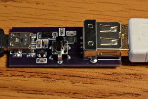
 Paul Stoffregen
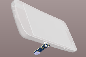
 Antti Lukats
Nice project ! i have the same issue with one of the USB-ports not powering. Anker send a new one without complaints and could keep the old one.
Guess what i'll be doing, but this struck my interest to make it a "universal" powerbank.
Any idea if this can pump out 12v1a ? i've seen a project that uses Quickcharge protocol to trick the controller into providing 12v over usb but i would like a passive way (removing some resistors as such)
Any idea's ?
XtremeHacker007