 andrew.powell
Okay, so this project has very little to do with Linux. In fact, is has nothing to do with Linux, or Zynq! I’m actually planning to change the format of this “project” ( or perhaps the project’s format has already been changed, depending on when you are reading this log ). I regularly do smaller projects as a way to focus on learning something knew. And, since I don’t want to end up adding a million different projects, this project page will be changed to include any sort of small embedded project! From this point forward, the individual projects under this project page will be added as separate logs!
On to what this log is really about…
The Idea: Learning the DMA Scatter Gather and Multi Channel Modes and Generating Samples from a Normal Distribution in a FPGA!
An important component in virtually any computer system is Direct Memory Access ( DMA ), how a peripheral can directly access main memory without the need to depend on a host device. Clearly, a very useful and practically necessary component. For my applications using Xilinx FPGAs, external memory access with the Xilinx AXI DMA is the fastest ( and simplest ) method compared to alternative solutions, for instance directly implementing a full master AXI interface ( excuse the redundancy )! So, I regularly use the DMA core so that my cores can access external memory. But, before the completion of this project, I would only use the AXI DMA to perform simple transfers, not relying on the more advanced, though more useful features.
The Theory: Box Muller Algorithm
Not much theory on SG operations, really. I will talk a bit more about my experience with SG in the implementation section of this log.
As briefly mentioned, the Box Muller algorithm is a method for generating normally distributed samples from uniformly distributed samples. There are two basic forms of the algorithm, the first of which relies on trigonometric operations, which are costly operations. The second form, referred to as the polar form, eliminates the trigonometric operations completely. I will only show the algorithm for the polar form here since this is the algorithm that is actually used.
Pretty simple, right? With HLS, it’s almost trivial to implement! I will discuss a bit more about the implementation in the next section!
The Implementation: Generate a Tone and Make Some Noise!
All the project does is generate a single tone and add normally distributed noise to the signal. The volume of the tone and noise can be changed with the pushbuttons, and the tone and the signal can be toggled altogether with two slide switches. The target hardware includes the Digilent Nexys 4 DDR development board, which contains a Xilinx Artix-7 FPGA. Connected to the board is a Digilent Speaker Peripheral Module, which uses an amplifier that can be driven by PWM.
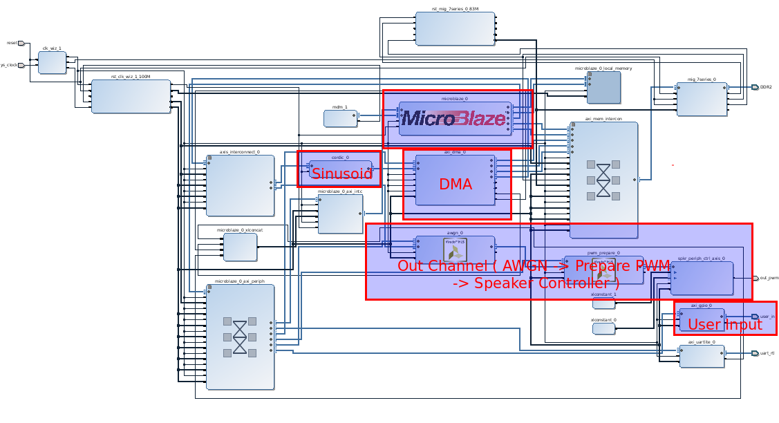 The general flow of the system is a follows. The host device, the soft processor MicroBlaze, first configures all the peripherals in the system. Through the DMA, a CORDIC core is then used to generate the samples of the sinusoid which represents the tone. Once the samples are acquired, several vectored SG write operations are configured to ensure the DMA will continuously feed the sinusoidal samples to the Out Channel.
So, my main challenge in this project can be boiled down to misunderstanding how the SG and Multi Channel modes work in the DMA. The reason for this misunderstanding can then be boiled down to my habit of skimming through documentation, particularly datasheets --- particularly LONG datasheets. I don’t think this is necessarily a bad habit, since in many situations the datasheet is mainly a reference. But, it can be dangerous, clearly. I’m sure any programmer / engineering / hobbyist / everyone hates having to read through a 100 page document just so they can take advantage of a core ( or class, function, device, etc. ) whose purpose can be summarized in a single sentence! In my case, I just wanted feed my peripherals some data from external memory! What’s even worse was that there’s already a driver. Some might reasonably say that should be good a thing! I wouldn’t have to write, and then debug, my own driver. But, provided drivers or libraries often give me a reason to read even less of the device’s datasheet.
But, exactly what challenge did I run into? Well, when I first configured all the DMA through the provided Standalone driver, I got it to work, sort of! Of course, “sort of” really means it didn’t work, but it kind of worked! Specifically, the core would continuously run in a loop of repeating transfers for a long period of time and then stop. And since I was using the DMA’s Multi Channel mode, I knew from skimming the data sheet there’s no way the DMA can even run in its cyclic mode! I was stuck on this problem for a while, and even the DMA’s status registers couldn’t help me. It’s always a bummer when you know there’s an error, but the device you’re using says otherwise.
So I read the entire datasheet ( honestly, it was more I skimmed less ) and found the source of my problem. Because I was running the DMA in its Multi Channel mode, the DMA is configured for only 2D transfers. Basically, this meant I needed to set an extra parameter in each of the buffer descriptors associated with each transfer! Funny enough, I probably could gotten away with not reading ( or skimming a lot of ) the DMA’s datasheet if I had followed the right example. Oh well, I definitely learned to pay closer attention to details!
Who am I kidding? I just got better at skimming! Back to the rest of this project...
Referring to the block diagram, the Out Channel itself consists of three components. The first, called AWGN for Additive White Gaussian Noise, is the HLS-implementation of the Polar Box Muller algorithm discussed earlier. Since the implementation is small, I will show a snippet of it here.
...
do
{
	u1 = ( ( float ) lfsr() ) / ( ( float ) (1<<16) );
	u2 = ( ( float ) lfsr() ) / ( ( float ) (1<<16) );
	u1 = 2.0f * u1 - 1.0;
	u2 = 2.0f * u2 - 1.0;
	w = u1*u1 + u2*u2;
}
while ( w >= 1.0 );

w = sqrt( (-2.0 * log( w ) ) / w );
gs[ 0 ] = u1 * w * ( ( float ) *stdd );
gs[ 1 ] = u2 * w * ( ( float ) *stdd );
...
The algorithm generates two pseudo-random samples, which means that the algorithm only needs to be executed once every two input samples! The function "lfsr" refers to the Linear Feedback Shift Register ( LFSR ) implementation. /* https://en.wikipedia.org/wiki/Linear-feedback_shift_register */
uint16_t lfsr()
{
static uint16_t cur = 0xACE1u;
uint16_t bit;
uint16_t ret = cur;
/* taps: 16 14 13 11; feedback polynomial: x^16 + x^14 + x^13 + x^11 + 1 */
bit = ((cur >> 0) ^ (cur >> 2) ^ (cur >> 3) ^ (cur >> 5) ) & 1;
cur = (cur >> 1) | (bit << 15);
return ret;
}Admittedly, my LFSR function is pretty much a modified version of the one found on Wikipedia. But, it does the job, which is to generate uni-formally distributed samples!The only problematic part of this implementation is the fact that the implementation is nondeterministic in terms of execution length, all due to the while-loop. This could be troublesome for a system that requires data before specific instances of time. Specifically, because this project is audio, the sound can potentially lag or distort if the algorithm runs for too long. The trigonometric form of the Box Muller algorithm is actually deterministic, but runs far slower and demands more resources. Would it have been sufficient? Actually, judging from the analysis the Xilinx HLS estimates, it would have barely passed in terms of latency.
Barely passing is VERY unsettling, however! Plus, I was worried about running out of DSP hard blocks. The polar implementation already eats up 34% of the FPGA’s total DSP resources alone. And, I’m guessing the trigonometric implementation would have at least doubled that percentage. In my experience with FPGAs, utilizing too much of a single resource leads to potential issues with routing, too.
The second of the three cores in the Out Channel is Prepare PWM. In spite of its name, this HLS-generated core doesn't actually generate the PWM signal that’s fed into the amplifier. The job of Prepare PWM is to simply convert the signed 16-bit output of the AWGN core to an unsigned 10-bit value.
The unsigned value is finally passed into the Speaker Controller, the third and last core of the Out Channel. Instead of HLS, this core needed to be developed in VHDL since it’s main job is to buffer samples in a FIFO, and output them at a consistent rate as PWM signals. Not sure if this is possible in HLS at this point, but it would be SUPER cool to have inline HDL, similar to inline assembly! Effectively, inline HDL would behave in a similar manner as assembly; for low-level needs, inline HDL could be used to implement hardware interfaces such as PWM or SPI, whereas the C/C++ code can still be used to take advantage of common but larger interfaces such as AXI!
Whelp, that’s it! :D
Anyone who’s interested in more specific details of the project can take a look at the Vivado 2016.2 project itself!
GitHub Repository: https://github.com/andrewandrepowell/scatter_dma
Discussions
Become a Hackaday.io Member
Create an account to leave a comment. Already have an account? Log In.