 Ianislav Trendafilov
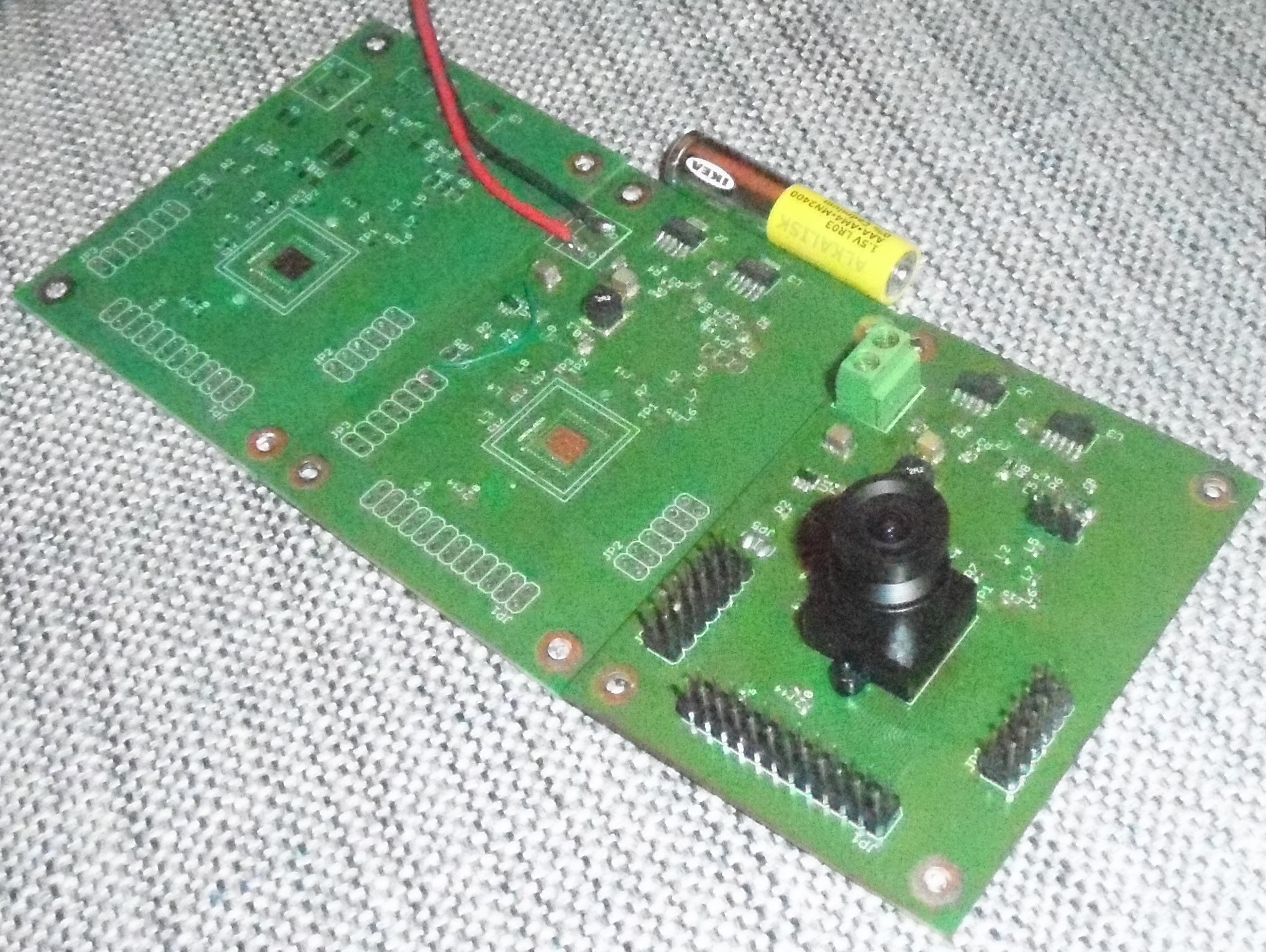
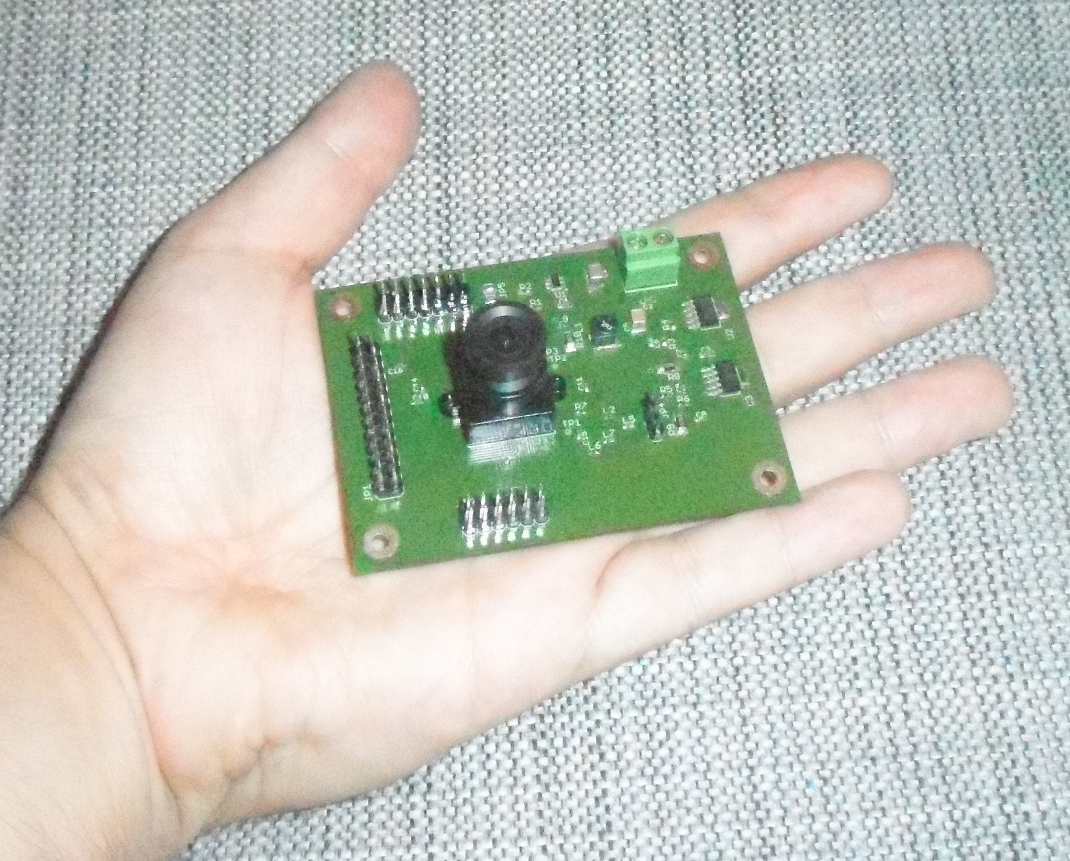
Time-Of-Flight is an active-illumination technique for object detectance and distance measurement. System requires an NIR light source (4xSFH-4715AS in my case), Analog frontend sensor (OPT8241) and digital transformation (I ill use custom FPGA program). Texas instuments offers a prebuild development kit for ~600$, but vendor lock-in with opt9221 is annoying. So I will do it with ~99$ De0-Nano-SoC and some custom boards.
0%
0%
3D-ToF scanner
Project uses OPT8241 3D-ToF sensor, CycloneV FPGA with HPS and Linux OS
Become a Hackaday.io member
Already have an account? Log in.
Just one more thing
To make the experience fit your profile, pick a username and tell us what interests you.
Pick an awesome username
hackaday.io/
Your profile's URL: hackaday.io/username. Max 25 alphanumeric characters.
Pick a few interests
Projects that share your interests
People that share your interests
 CarbonCycle
 silver2row
 Yann Guidon / YGDES
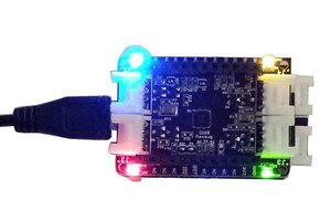
 Pattern Agents
What's the status? Is this project still active?