Irene Sanz
-
Robotic Guide application
08/17/2016 at 16:53 • 0 commentsThis is the first real-world application we chose to do. As a robotic guide, Tabbot will be able to tirelessly give tour after tour around museums, or usher visitors into your office or waiting room for you.
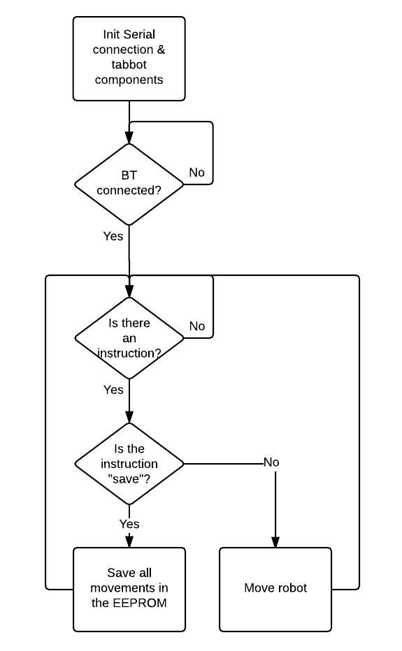
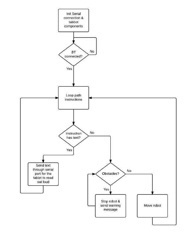
To program the path to follow, one simply controls the robot from the RoboControl app and pushes the 'Save' button when done. This will save the trajectory into the boards EEPROM. Once connected to the computer, it will print over serial port the full formatted path variable ready to be copied to the guide sketch. There the user can add messages at key points for the tablet to read.
![]()
The reason for dividing it into two sketches is simply the memory size, in the future the EEPROM will probably be replaced by an SD card and full sentences will be able to be saved, instead of having to rely on the flash memory.
The second sketch waits until a connection is established and then goes through the path instructions, moving and talking until somebody gets in the way or the tour is done.
![]()
-
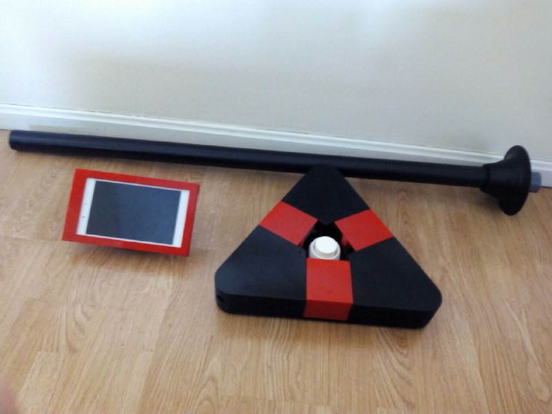
Tabbot v1.0 complete!
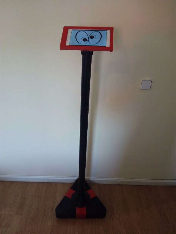
08/16/2016 at 17:05 • 0 commentsThe build is finished! We printed the missing parts, re-printed a few (don't mix high printing speeds with low infills!) and painted and trimmed the tube to the right height.
![]()
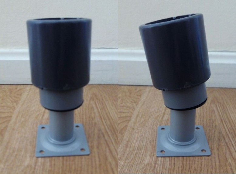
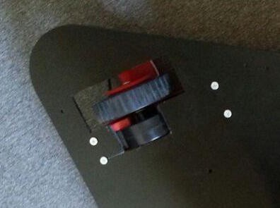
We had to re-design the tube holder, since we initially went for a combination of
off-the-shelf PVC and metal adapters held together by a rubber fitting which of course
failed miserably, so we followed the KISS methodology and printed a single
piece that did the job. Below we can see what we expected to happen and what actually happened.
![]()
This also presents the advantage of portability: the two 3D-printed parts holding the
tube in place do so by friction, so while in the future we may want to glue the pieces
together to make it more robust, for now we can disassemble the robot in three
convenient pieces for transport.
![]()
-
Electronics
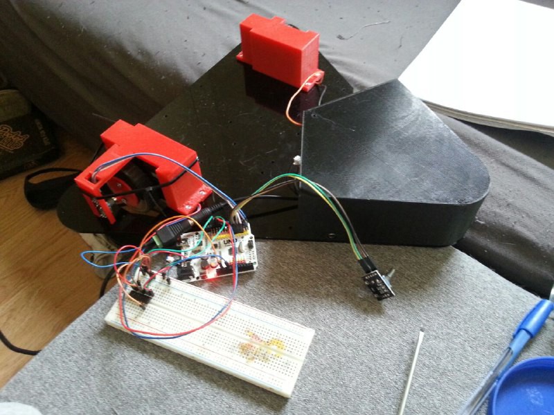
08/16/2016 at 16:45 • 0 commentsAs we mentioned previously, the brains of the robot is an arduino board. While very convenient to program, and so to share, it needs at least two H-bridges to drive the motors which can't be plugged into the board.
The first thing, after measuring the motor's current requirements and selecting the correct driver, is to connect everything into a breadboard to ensure everything works properly.
![]()
After the first run, both boards slid off the robot and disconnected, so obviously that wouldn't work and we had to move on to a prototype board.
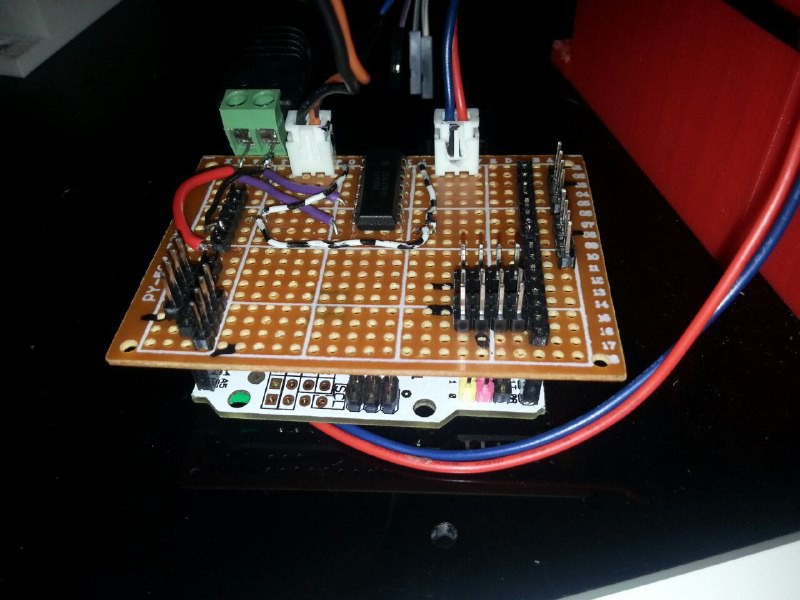
Here we can see the shield with the double H-bridge ic, power jack, motor cables and all the broken-out pins for the encoders, ultrasonic sensors and bluetooth. We also added a couple of velcro strips to secure the assembly in place.
![]()
After a couple of days of work the bootloader got corrupted when uploading and we had to make a small cut in the shield to gain access to the ICSP header to fix the problem.
If no more problems arise, all of this will be taken into consideration when designing the final PCB.
-
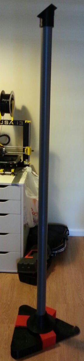
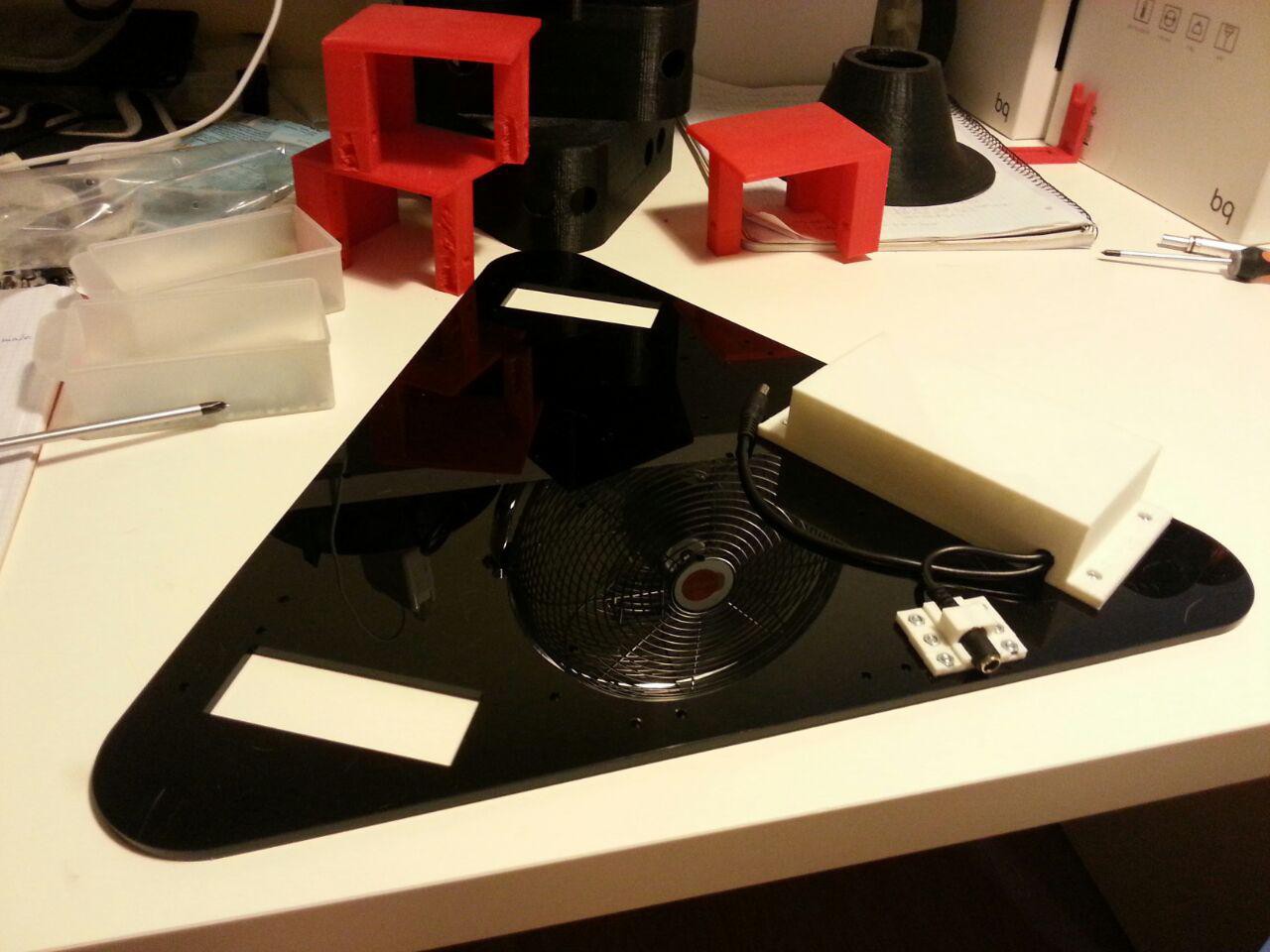
Building the base
08/11/2016 at 16:06 • 0 commentsSo... more news on Tabbot! I've been printing the different pieces and adjusting some tolerances on the way. This picture gives you some idea of more or less how it should look. The tube is not cut to the right distance and some of the base pieces are just the first layers of a print that went wrong, but you can start seeing its future form! :)
![]()
And also, the methacrylate base is finally here! Let's start putting it all together!
In this picture you can see the battery holder + charger supports already on the methacrylate base. On the background, the different covers of the base are already printed as well. It is taking shape!![]()
Everything is fitting perfectly, except for the motor. I didn't take into account a little bump it has on the bottom and had to manually cut a pocket in each side of the base:
![]()
Nevertheless, apart from that little drawback, now its ready to start moving!
-
First design finished!
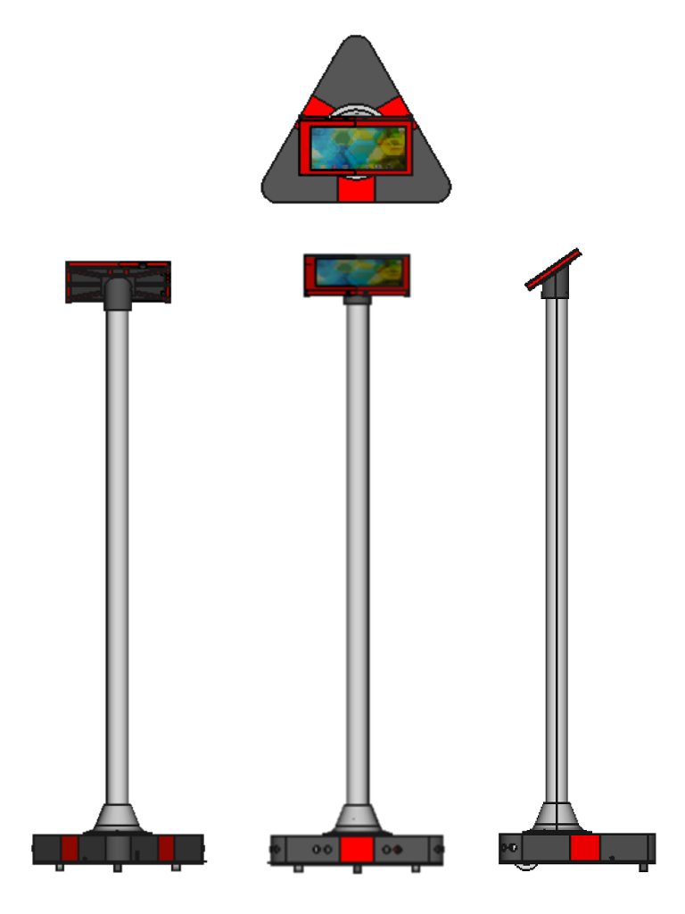
08/11/2016 at 15:41 • 0 commentsAfter some work and different initial concepts, the first complete Tabbot design is finally finished!
![]()
These are the different views of the 3D model:
![]()
It has two motors with its wheels and a third castor wheel for support. The base is laser-cut acrylic and the tube supporting the tablet, PVC. The rest of the pieces are 3D-printed. The whole model has been designed using FreeCad.
Next step: print everything, buy the PVC and cut the acrylic!