0%
0%
Load Frame Update
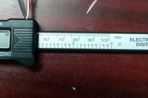
Add digital output to a mechanical testing load frame using arduino.
 Mark Bradshaw
Become a Hackaday.io member
Already have an account? Log in.
Just one more thing
To make the experience fit your profile, pick a username and tell us what interests you.
Pick an awesome username
hackaday.io/
Your profile's URL: hackaday.io/username. Max 25 alphanumeric characters.
Pick a few interests
Projects that share your interests
People that share your interests


 Michael Skrepsky
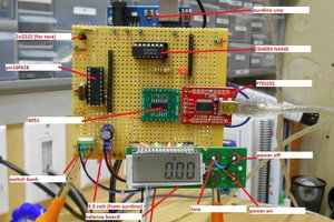
 will.sweatman
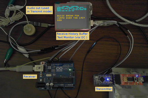

Just curious - any additional info on this project? I'm now doing something similar. (Full disclosure: this is somewhere between a hobby project and something work-related. I thought I'd give this a shot before going out and spending the $ for a pro-built system.)