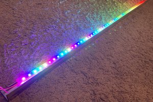
We purchased a couple of WS2812B Led Rings and thought this was a cool project to make.
Initial development in the project was done using nodemcucu dev board.
The device hosts an esp-01 inside it, because only a single I/O is required.
It took a couple of prints to get the fitting snug and well placed, to get all the wires and parts inside fit snug, without much shaking.

 Jon Kunkee
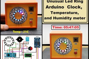
 mircemk
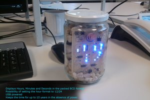
 Marius Taciuc
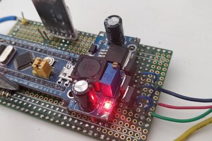
 Laurynas Ubys
Where are the files for 3D printing?