 agp.cooper
Hardware Complete
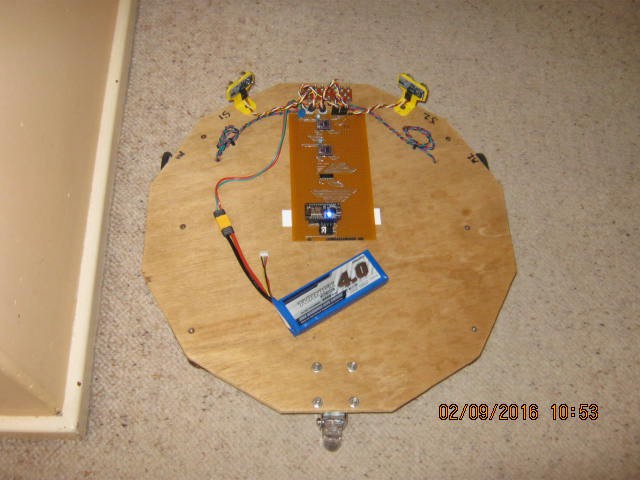
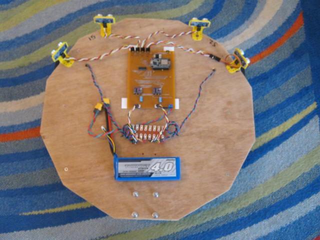
The hardware is complete, here is the testbed:
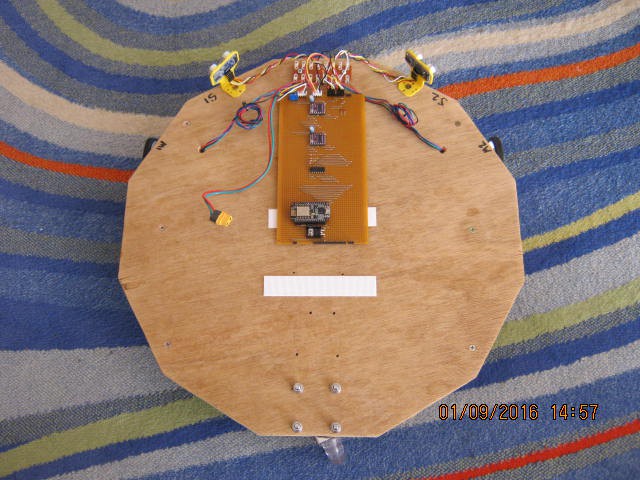
The battery is missing (being recharged after a day of debugging).
The white strips are Velcro.
The testbed has been set up as an autonomous robot using the ultrasonic sensors to stay away from objects.
Software Problems
It basically works but there a problems (what is new!).
Currently making sure the sensor and stepper drive logic works.
The main problem is that the sensor (or sonar) ticker interrupt (every 250 ms) interferes with the stepper pulse ticker interrupt (every 10ms) as stepper pulses appear to be lost). I assume that the sonar ticker interrupt (that can take up to 40 ms (with time out) to return) is blocking stepper ticker interrupt. The ticker interrupts do not appear to be the same as normal interrupts as the sonar routine waits for a real interrupt on D3 and is working.
It is not unreasonable to assume that Ticker is blocked while servicing a ticker interrupt.
Worked it out.
I moved the pulse timing loop out of the interrupt routine and into loop(). No difference!? Okay worked it out. Ticker is not interrupt based but "Blink without delay()" based. Better than nothing I suppose. Okay, recoded on this basis and the motors work fine but the sonar no longer works.
Motor Noise
The sonar work fine until I turn on the steppers. The interrupt line must be picking up the stepper noise. It was okay before because the sonar blocked the stepper pulse during the echo period.
So now I have to research noise suppression.
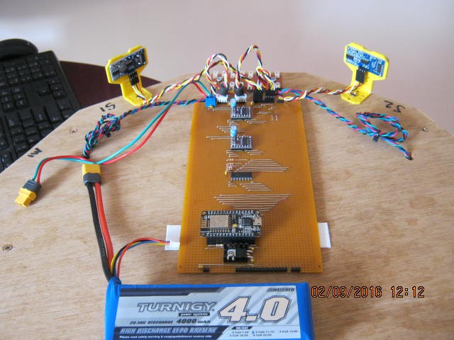
Noise Fixes
- Added 6 decoupling capacitors (0.1uF) to the 3.3v, 5v and power in lines.
- Added 4 decoupling capacitors to the DRV8825 motor outputs (my steppers have 58 mH inductance for each phase so the resonant frequency would be about 2 kHz, so no problem).
- Add two ferrite beads to the stepper cables (why not!).
- Twist paired all the cables.
See image:
- The EPS-12E is now okay with serial while the motors are running (five stars)
- The steppers are much easier on the ears (three stars)
- The ultrasonic sensors are just as bad/unreliable with the motors running or not (three stars).
Ultrasonic Sensors
I think I forgot how bad ultrasonic sensors are! I did a sonar project a while back so I should have known:
Filtering Bad Sonar Reads
Filtering the bad reads is problematic. Simple averages don't work well.
With the sonar project I used the median value of three sequential reads.
This time I used two similar consecutive reads with "too far" over-rides.
This work as well as can be expected, but the code need tuning.
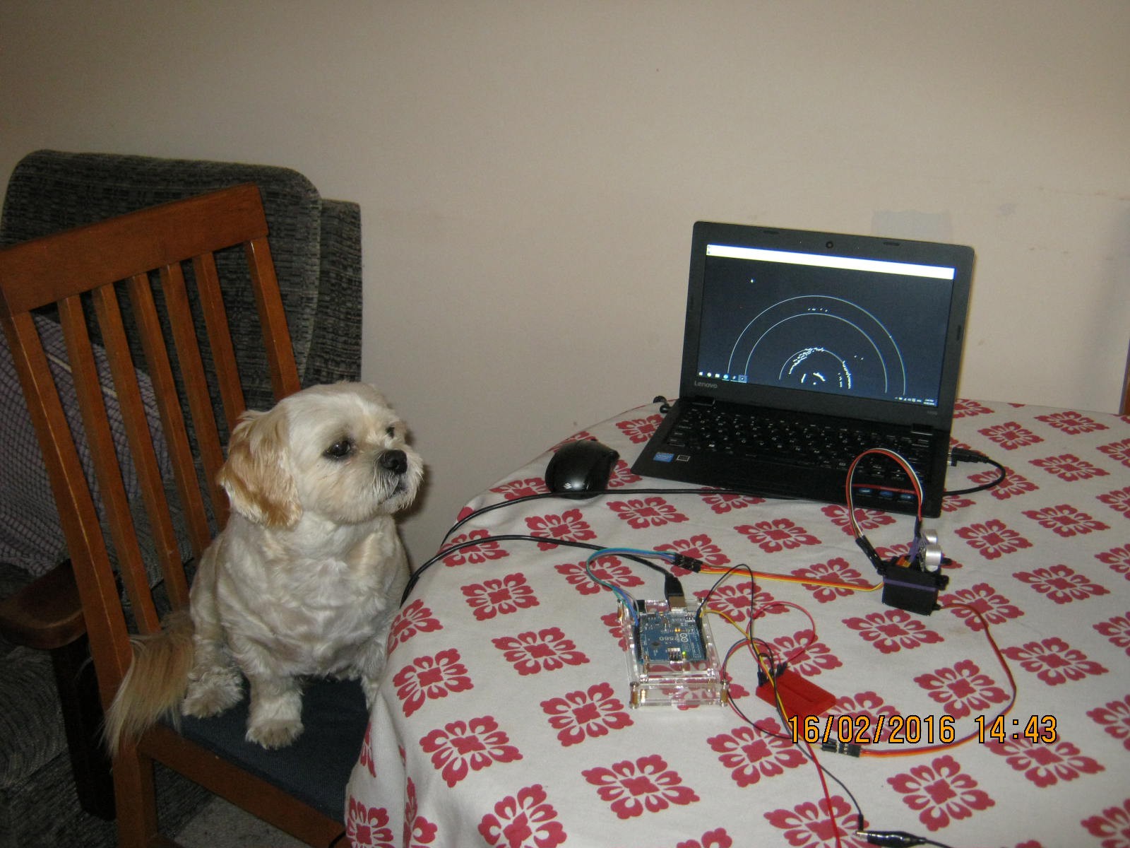
It still struggles to get through the doorway and still crashing into walls.
Here it is when it works (turning to avoid the wall):
Sensor Check
I thought it was time to draw up the sensors to "engineer" the direction they point and the correct range trigger.
So here is my sketch:
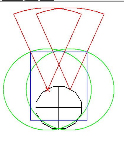
I should point the sensors forward and set the range to 50 cm (assuming a 45 degree aperture based on a datasheet I have).
This gives full frontal coverage and 640 mm wide window.
But the problem is that the sensors do not detect the walls as the angle of incidence is too low (~22.5 degrees).
I need four sensor! Two short range (at 60 degrees with 15 cm range) to detect the walls:
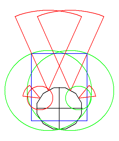
The forward sensor worry me a little because they are only 14 cm off the ground so expecting a range of 50 cm not going to be reliable (some back-scatter off the ground is likely).
Board Redesign
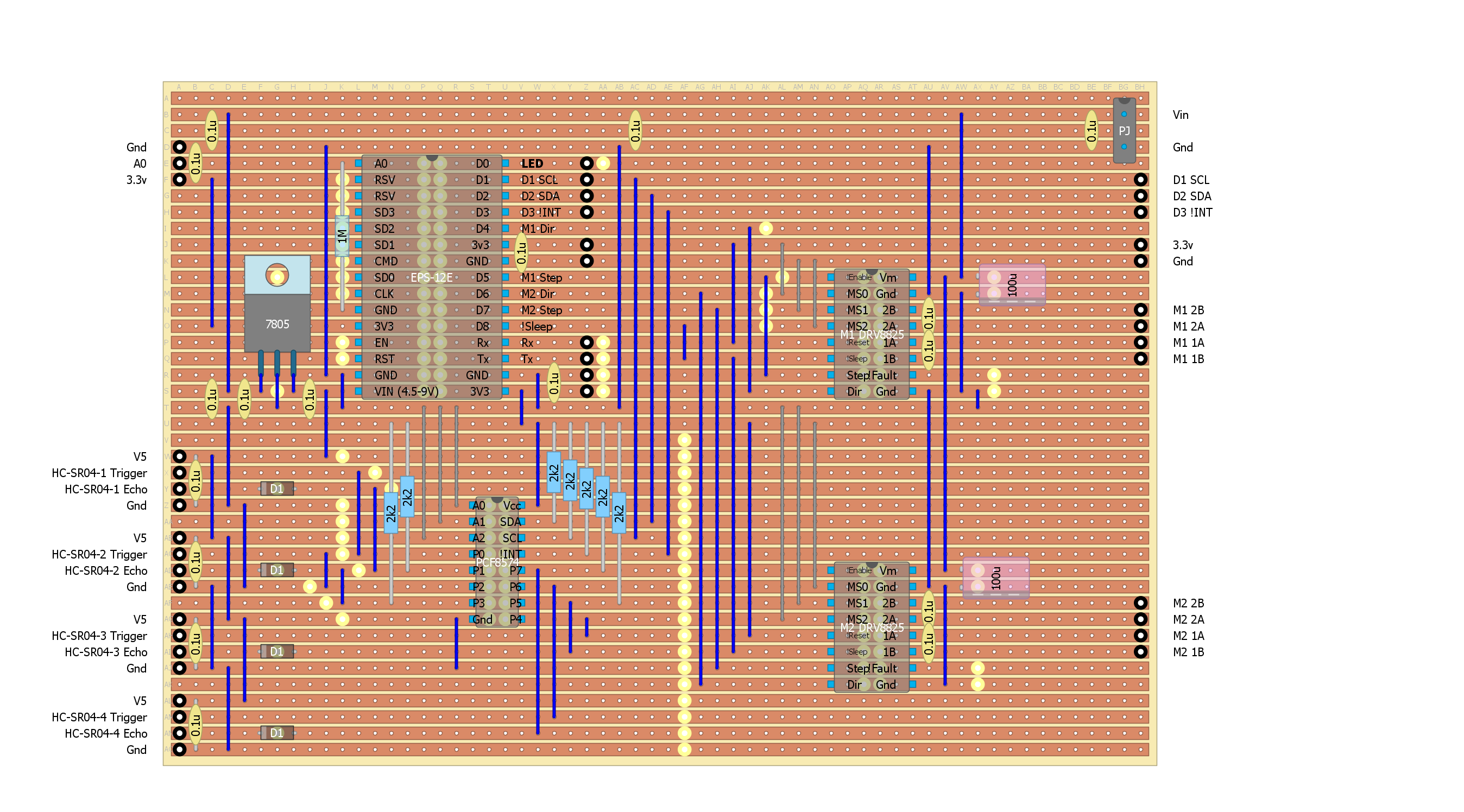
It looks like I will need four ultrasonic sensors and the PCF8574 is the obvious choice for managing these.
I have four spare ESP-12E digital pins so I should move the two sets of stepper direction and step lines off the PCF to make room for two more ultrasonic sensors.
The board layout needs a rework anyway. It would be a good idea to move the sensors away from the DVR8825s.
So back to the drawing board!
Spent a day resigning the board. Here is the design:
Had some work to do at the partners house (fixed 4 leaking taps and swapped out the washing machine).
But I did manage to find 4 hours to assemble the board.
It powered up okay (good sign) but I need to re-code the ESP-12E for the new board.
How hard is this meant to be?
Now I have to say it has been surprisingly difficult getting this rather simple project working.
This is the sixth board I have used:
- Arduino UNO and 2x L298N (these driver boards are useless)
- Arduino UNO and 2x Monster Motor Boards
- Ardunio Nano, Bluetooth (not recommended) and 2x A4988
- Wemos D1R1 (WiFi) and a Protoneer V3 CNC shield using 2x DRV8825
- EPS-12E, PCF8574, 2x DRV8825, 2x HC-SR04
- EPS-12E, PCF8574, 2x DRV8825, 4x HC-SR04
I have run into electrical noise issues, real headaches from the stepper motor noise and unreliable sensors.
Although I destroyed the third board with a loose battery wire, at least I have not destroyed any other board so far.
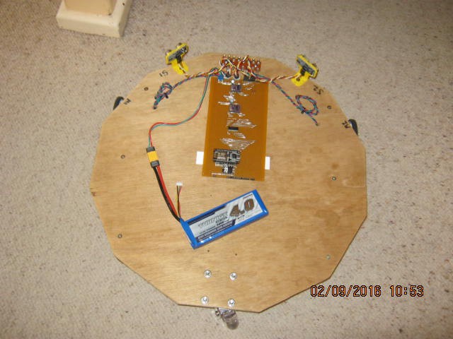
New Code and New Board Installed
I coded the ESP-12E for the new board this morning.
Those ultrasonic sensor give me a headache and make me nauseous.
But the four sensors are working after finding I forgot to solder a ground link.
Have to stop as I am going out for Father's Day lunch (best not to be too sick!).
Here is the test-bed ready for testing:
Ultrasonic Sensor Aperture
What I did find out is that the minimum angle of incidence off a plywood plate is about 60 degrees.
This also suggests that the effective angle of aperture for these sensors is more like 30 degrees.
Checking with a hand about 15 to 20 cm away from the sensor and it only detected the hand inside 15 degrees (i.e. a 30 degree aperture).
So the wall sensors will need to point at 75 degrees rather than 60 degrees.
I had a noisy sensor, the one with the cable extension (removing the extension resolved the noise).
The board and code seems to be working within expectations for the sensors.
If I had realised that the ultrasonic sensors had such a small aperture I would have gone with the sonar version using a servo to scan the path ahead.
Motor Control
The motor control works as expected except that the serial will not work with ticker running a 10 ms clock.
Overall Performance
In a word: dreadful. Certainly software tuning will help.
It can detects forward objects and the presence of a wall but it is very slow to respond.
Filtering out the bad readings takes time (assuming that is the main issue).
It would have been easier to use a servo and a sonar set up.
Next Steps
Not sure what to do next. It is just not good enough at the moment.
The hardware seems to be as good as can be expected.
I was checking the code and found some errors and better ways of doing things.
It is looking more promising.
I am going to wear earmuffs from now on as the ultrasonic sensors are driving me crazy (particularly if I pulse them slowly).
I hate these ultrasonic sensors
I re-coded the sensor loop to stay with a sensor until it got two similar readings (within 10 cm) before moving to the next sensor.
Also anything beyond 100 cm is set to 100 cm.
Depending where you point the sensor it may never return consistent readings.
Yes the entire stepper system was turned off.
Sensor 3 was the worst but all the other sensors could be made to fail.
Thinking about how it might be failing (i.e. time out), I slowed the cycle down from 50 ms to 100 ms.
Now it does return (sometimes after four or five fails).
Time out is meant to be 38 ms but obviously it is much longer.
Checked the power supply line with the scope and it is clean.
Sensor 3 has timeouts up to 110 ms. I replaced this sensor but no real improvement.
Tried shielding the sensor electronics with aluminium foil, no improvement.
These Chinese ultrasonic sensors are useless
I don't think I can fix these sensors. They give random readouts when out of range.
I would guess they have automatic gain control and end up listening to noise when out of range.
Thus the random out of range readings.
I bought 8 of these (3 different brands) and 3 have already been binned.
I can't even fit the last two to the mount as the PCB mounting holes are too small.
I binned 2 of 3 sensors (two different types) just for my sonar project.
Now there are more expensive (non-Chinese) sonar sensors out there.
Very likely these will work perfectly but the at more than ~$50 a piece I am not keen to try.
DIY Ultrasonic Range Sensors
If I want ultrasonic range sensing I will have to build my own.
After the sonar project I did buy a packet of sensors with this in mind.
I am not looking to sense far objects in this case so a high power transmitter circuit and a low noise pre-amplifier are not required.
More research! So this project is on hold until I come back from holidays.
AlanX
Discussions
Become a Hackaday.io Member
Create an account to leave a comment. Already have an account? Log In.