 agp.cooper
DIY Sonar
First lets start with the expected signal level.
Based on the 400RT160 datasheet (http://www.robot-electronics.co.uk/files/t400s16.pdf) and the Pro-Wave Electronics Corporations application note (http://www.prowave.com.tw/pdf/an0508309.pdf) the approximate signal level is in the order of 1 to 10 mV:
| 400SR/T400 | |||||
| Transmitter SPL | 117.0 | 10v rms at 30cm | |||
| Power adjustment | -6.0 | 5v rms | |||
| Distance loss | -28.5 | =20*log10(30/x) | Distance | 800 | cm |
| Wave absorption | -1.6 | =-0.002*cm | |||
| Receiver sensitivity | -57.0 | 3.9k load | |||
| Conversion uBar to V | -74.0 | ||||
| Signal | -50.1 | dB | |||
| Signal | 3.119 | mV |
Here I have assumed 5v rms transmitter voltage rather than 10v rms as per the standard.
The sensor input impedance is 3.9k ohms.
The signal input (3 mV) suggests a minimum receiver gain of 60dB (x1000) is required.
I have designed two circuits (more options are available for consideration).
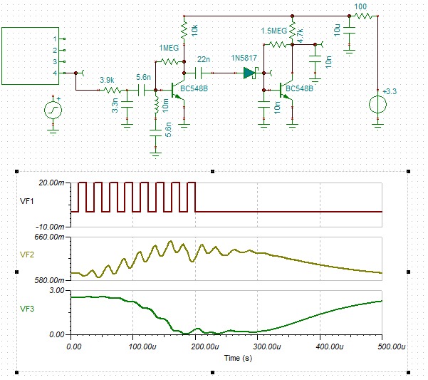
The first is a two stage transistor amplifier (74dB gain based on the Tina simulation) followed by a diode detector. For this circuit I assumed the sensor impedance was about 20k as I had not found the right datasheet.
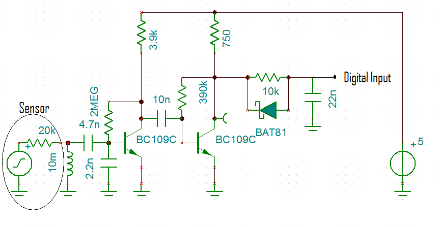
A very important note is that I have not designed the supply noise filtering for this circuit. With 74dB of gain (x5000) and the input in-phase with the output, the risk of feedback is almost certain.
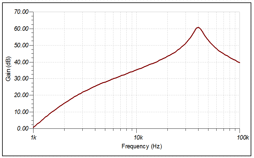
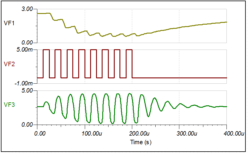
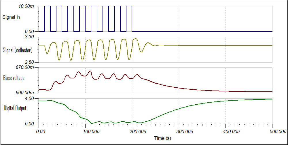
Hers is the frequency and transient analyses:
The second version is less sensitive but should not suffer feedback oscillation:
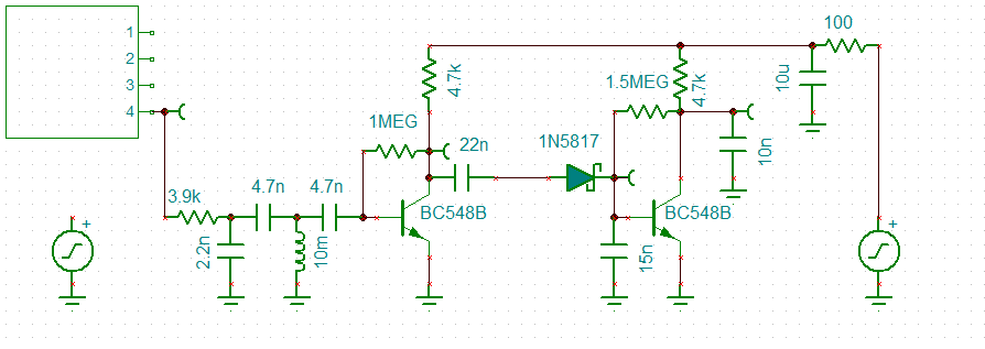
The choice of detector diode determines the receiver sensitivity. A germanium diode would work best followed by schottky diodes and lastly conventional silicon signal diodes.
Preliminary Transistor Amplifier Design
The preliminary transistor amplifier design is as follows:
| Preliminary Design | Value | Units | |
| Transistor | BC548B | ||
| Beta (2mA) | 290 | ||
| Vs | 5.0 | v | |
| Vc | 2.7 | v | |
| Rc | 4.70 | k | |
| Ic | 0.489 | mA | =(Vs-Vc)/Rc |
| Beta | 236 | =log10(2/1000)/log10(Ic/1000)*Beta(2Ma) | |
| Zin | 12.1 | k | =Beta*25/1000/Ic |
| Rb | 0.99 | M | =(Vc-0.65)*Beta/Ic |
| Av | 108 | =Vc/25*1000 |
The design formula works okay except that Tina predicts a much lower gain.
Still it is a useful starting point.
Pre-selection LC filter
In both these sonar receivers I have used a pre-selection LC filter to reduce out of frequency response and to match the sensor to the transistor input impedance.
I used capacitor tapping to scale up the impedance in the two circuits:
RL~RS*((C1+C2)/C1)^2, where C1= 4n7F and C2=2n2F in circuit 2
In this case I used Tina to determine the exact capacitor values but there are formulas for this if you look on the Internet.
Another design
I also played with this one:
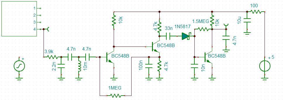
And:
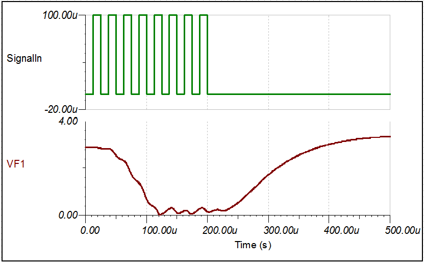
The low limit of detection is in the order of 100uV which is a bit of overkill.
The second version looks about right to me if I use a Ge diode (or a Ge silicon clone).
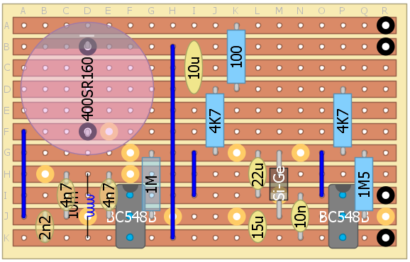
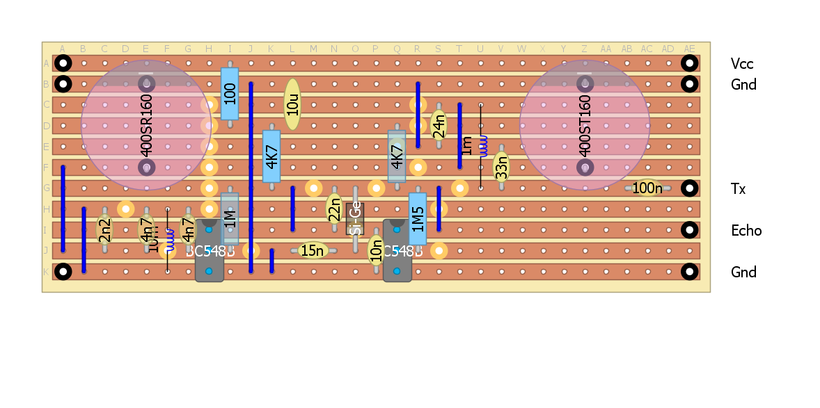
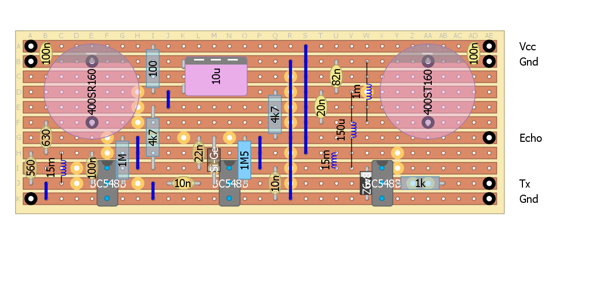
Probably time to make a prototype using strip-board, here is a layout:
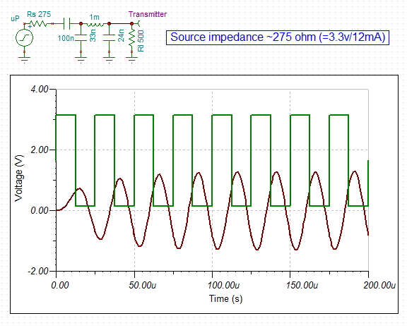
Transmitter
Based on the limited data on the EPS-12E the digital pins can source/sink 12 mA. This is similar to the AVR specification. So an estimate of the "source" resistance is 275 ohm (=3.3v/.012A). The effective source resistance is probably lower. The ultrasonic transmitter has a load impedance of about 500 ohm (based on the datasheet). So I matched the source impedance ad load impedance using a Pi network and updated the strip-board design. I calculate the output power to be 1.6 mW (2.55v pp based on Tina). Here is the Tina schematic:

Here is the strip-board design:
Checking the range:
| 400SR/T400 | |||||
| Transmitter SPL | 117.0 | 10v rms at 30cm | |||
| Power adjustment | -20.9 | EPS-12E single pin | 3.3v into Pi network | ||
| Distance loss | -4.9 | =20*log10(30/x) | Distance | 53 | cm |
| Wave absorption | -0.1 | =-0.0019*cm | |||
| Receiver sensitivity | -57.0 | 3.9k load | |||
| Conversion uBar to V | -74.0 | ||||
| Signal | -40.0 | dB | |||
| Signal | 10.0 | mV | Receiver detection limit | ||
A return range of 53 cm (26.5 cm one way) is practically unusable!
Okay, I either increase the transmitter power or increase the receiver gain.
Increasing Receiver Gain
Looking at the receiver I had a play with reducing the supply voltage down to 3.3v to eliminate the need for a 5v supply. The sensitivity "reduced" to 20 mv (from 10 mv):
It would seem that I should revisit the two transistor pre-amp schematic.
Increasing Transmitter Power
In order to increase the transmitter power I have to reduce the source resistance by buffering. Many options but here is one that I looked at:
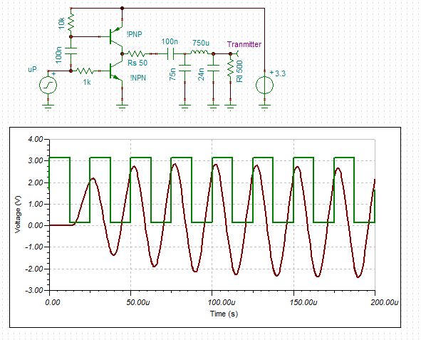
The output is 5.5v pp which equated to 6.4 mW into a 500 ohm load.
In theory you could push this circuit for higher power but the Q increases rapidly making tuning necessary and tricky. Higher Qs also slow the power ramp up.
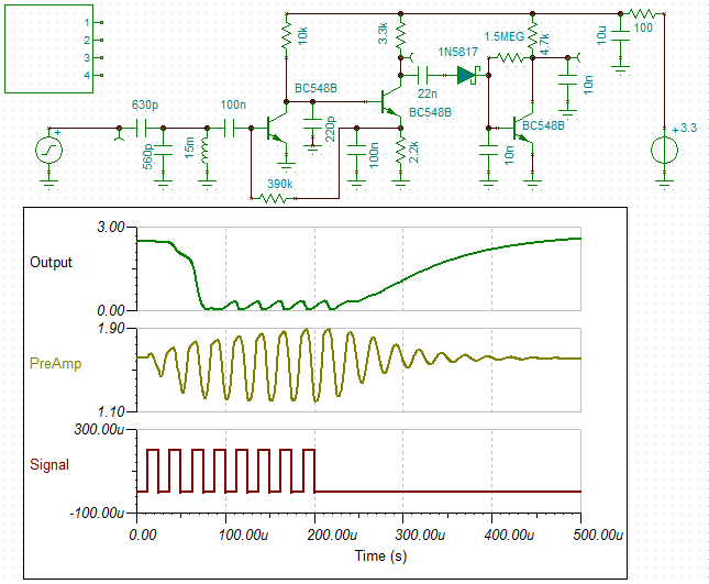
Revised 3 transistor design
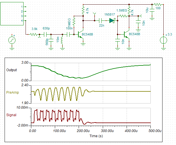
I have revised the design for 3.3v and a simplified "T" high pass filter matching network. I have added a 220pF to roll off the high frequencies faster. Here is the schematic and the response to a 200 uV signal:
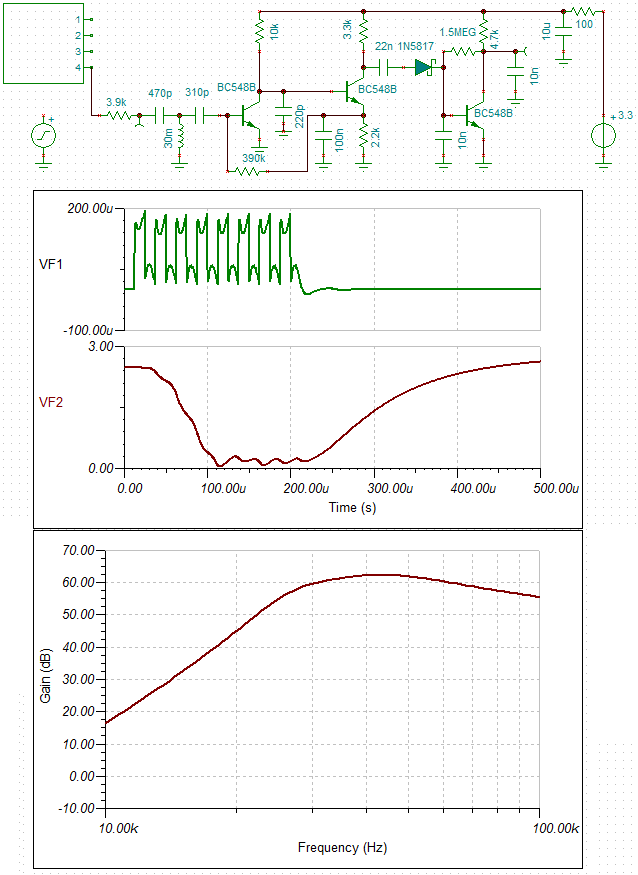
(Note:the 3.9k resistor on the input is part of the sensor.)
The receiver can detect a 200uV signal which is more than enough for the low power transmitter:
| 400SR/T400 | ||||||
| Transmitter SPL | 117.0 | 10v rms at 30cm | ||||
| Power adjustment | -20.9 | EPS-12E single pin | 275 ohm source impedance | |||
| Distance loss | -28.5 | =20*log10(30/x) | Distance | 800 | cm | |
| Wave absorption | -1.6 | =-0.0019*cm | ||||
| Receiver sensitivity | -57.0 | 3.9k load | ||||
| Conversion uBar to V | -74.0 | |||||
| Signal | -65.0 | dB | ||||
| Signal | 0.6 | mV | Detection is about 0.2 mV | |||
Now I have to source the inductors and capacitor values I have chosen and then update the strip-board design.
Strange
Well I was looking at what inductors I had and what I had to buy.
A 30 mH would be an ebay order (2-3 weeks) but I had some 15 mH. So no problem, just double them up.
But I though I would check if I can come up with a 15 mH design.
Now, I had noticed that the webpage I was using gave component values that were a bit off (peak at 30 kHz instead of 40 kH etc). I had countered this by optimising the design in Tina (slow but effective).
Up until now I thought it was due to the influence of the transistor.
But i noticed that the components values where not the same as a practically identical but different webpage.
Upon further investigation (and calculating the component values by hand) I found the webpage I was using was wrong. Tina said my calculations were correct.
So I started using the new webpage but even then some of the networks gave wrong answers. I some cases the component value labels were swapped around.
So I built a spreadsheet for the calculations. All good. I worked out a band-pass network using just one 15 mH inductor:
Updated Transmitter
Next was to check the transmitter.
I decided to look at a single transistor design using a collector "choke".
A two stage design is required else the Q would be too high.
Here is the design I can up with:
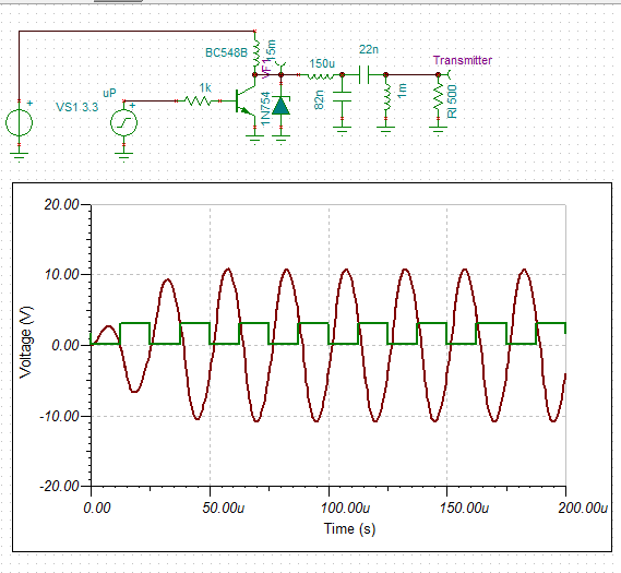
Because the circuit is driven by a square wave, the "choke" generates inductive voltage spikes.
I tried a capacitor at the base of the transistor (did not work) and a diode across the 'choke".
The diode worked but I was still concerned about the inductive spikes (~0.7v) superimposing on the power supply.
The final design uses a 6.8v 400 mW zener to clip the inductive spike.
Even Stranger
Following is the Tina simulation with the zener diode:
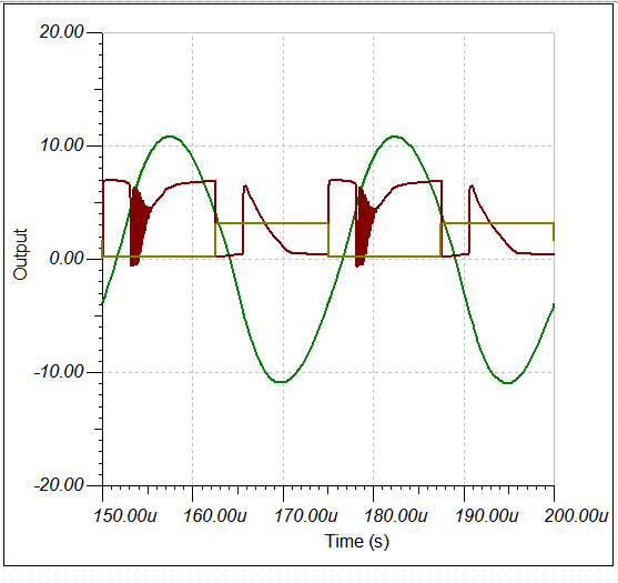
You will notice the ringing (~5.3 MHz, this should not be a problem).
What you will not know is that the output voltage (21.6v pp) has increased (from 17.3v pp) when the zener was added.
So the inductive power has been put to good use!
The output power has increased from 75 mW to 116 mW.
I have heard of parametric amplifiers but I am still quite astonished.
Updated Signal Maths
| 400SR/T400 | |||||
| Transmitter SPL | 117.0 | 10v rms at 30cm | |||
| Power adjustment | -2.3 | EPS-12E single pin | 275 source impedance | ||
| Distance loss | -28.5 | =20*log10(30/x) | Distance | 800 | cm |
| Wave absorption | -1.6 | =-0.0019*cm | |||
| Receiver sensitivity | -57.0 | 3.9k load | |||
| Conversion uBar to V | -74.0 | ||||
| Signal | -46.5 | dB | |||
| Signal | 4.8 | mV (rms) | |||
So with the new transmitter, the expected signal is about 5 mV (rms) at 800 cm return distance.
So I can use the two transistor receiver as it is sensitive to about 5 mV (pp):
Back to the strip-board design!
Here is the latest design layout:
Parts
I wandered down to the local electronics shop and purchased enough components for 5 sets of sensors.
The only hiccup was that the bag of sensors that I order on ebay last February (which were meant to be pairs) were all transmitters.
Still I have two other sensor receivers that I can use for test-work..
So I am not going to be able to finish the fours sensors I need for the Dalek in the next two weeks. Not good. Time is running out.
AlanX
Discussions
Become a Hackaday.io Member
Create an account to leave a comment. Already have an account? Log In.
Hi K,
Thanks. I have seen your post on ultrasonic sensors before.
I had a look at the datasheet and they claim up to 1 ms of ringing?!
I also had a look at the schematic and it uses a stepped gain control.
Less gain at first and more gain later.
My problem appears to be with out of ranges signals being random.
I suspect the gain switching is causing false signals.
But really I have no idea why these things don't work properly!
My set up was to repeat reading the sensor until I got two sequential reads within 10 cm.
It fails when out of range even though anything more than 100 cm is set to 100 cm.
Some sensors are better than others but they all fail!
That is why I have given up with these sensors.
I am pretty sure that there is not much more I can do (within reason) with noise shielding etc.
The signal is about 1 mV so I struggle to see why it is so hard!, it is not micro-volts.
I have spent a lot of time working through the receiver and transmitter designs.
It was probably a mistake not going the the Op Amp route as the design time would have been faster (single supply and bandwidth may have been a bit more of a problem however).
I am currently updating the strip-board design so I may get a test run in a few days.
I hope that it works as expected.
Regards AlanX
Are you sure? yes | no
I reuse cheap transducers from Chinese modules so the transmitter rings a lot. A better one would have helped, but they cost a lot more. I use a scope for these type of work as it is electrical as well as mechanical - even PCB stiffness/mounting makes a difference on the amount of vibration transmission across the PCB.
For the range finder mode, I have no gain control, but use the on-chip A/D based window comparator with a stepped threshold based on what I measured on the scope. It works reasonably well for distance measurement. I also have to grab the audio samples for the sonar mode, so I don't mess with the analog signal path.
I got lots of bandwidth with the LMV324 at 3.3V with a virtual ground (rail to rail output low voltage version). Because I am dealing with low voltage, rail to rail swing is essential. BJT and even old LM358/LM324 just won't do.
Sometime you might have to swallow the pride because of deadlines. Just use those Chinese modules to make those visiting kiddies giggle.
Are you sure? yes | no
Hi K,
Thanks. I was thinking of using the old sensors from the Chinese modules.
I was checking my ebay order and I found the sensors are TCT40-16T/R and not the 400ST/R160 that I thought. So my impedance estimates are off. So another design/check pass. Even so I am pretty settled on the design subject to it actually working. I intend to assemble one tomorrow.
The reason I did not use op-amps was because I wanted single supply and I assumed (incorrectly) that low noise was important.
I am a bit dated with op-amps, the last time I used them (1980s), a TL074 was magic!
I can understand the idea behind the gain stepping but it seems rather pointless in practice.
I considered using an analog pin but the ESP-12E only has one so I want to keep it for something else.
I have read somewhere that vibration was a problem. Once I have something working I will design a PCB board. It should help.
Any ideas why these Chinese modules suffer false triggers (mostly when out of range)? I would really like to understand what is going wrong.
Reading the datasheet for the TCT40-16T/R the receiver impedance seems to be 2100 ohm and the transmitter 400 ohm. The reference to 900 ohm throws me!
Yes those Chinese modules are not much good for anything except for kids!
Sound like a good project: ATTiny85 (DigiSpark) + HC-SR04 + LED/Buzzer + Plastic Box + blindfold = Lots of fun for kids.
Regards AlanX
Are you sure? yes | no
To be honest, I haven't actually play with the unmodified modules directly. I only try to reverse engineer them, and reuse the transducers as they are cheaper than buying the same transducer from China.
Open the image in another tab/window to see the full size for the reverse engineered schematic.
I have not see noise problem for out of range in my design, so it is specific to the module. It could be a trigger threshold issue. The module use a simple RC (C8, R11) as a variable threshold for U2A. As the cap C8 discharges to steady state, the threshold might get too sensitive for out of range?
R4 injects signal back into the virtual ground. In my design because I also crank up the overall gain and use proper values for the filter and somehow that caused oscillation. I fix it by connecting R4 directly to AGND.
LVM358/LMV324 that I am using is the 2nd cheapest low voltage, rail to rail part on digikey with GBW of 1MHz. TL074 has pretty decent specs even today. Just that it requires higher voltages and not rail to rail.
For ultrasonic at 40kHz, I can get about 20X or so per stage. A preamp, filter and another amplifier stage to get a few hundred times gain.
Are you sure? yes | no
BTW The spice model I used here for the transmitter predicts the ringing effect of the transmitter which corresponds to my measurements.
https://hackaday.io/project/5903-sonar-for-the-visually-impaired/log/18392-that-old-spice-magic
Are you sure? yes | no
FYI I have done a bit of work with those sensors. You have to watch out for the transmitter as it will ring long after the initial few pulses and also the physical vibration can travel across the PCB.
https://hackaday.io/project/5903-sonar-for-the-visually-impaired/log/19976-ultrasonic-module-hacking
Are you sure? yes | no