 agp.cooper
Conned Again
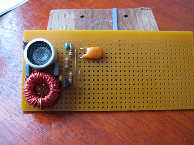
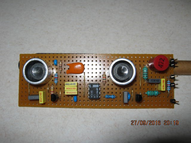
I bought these 15 mH inductors many many years ago. Finally I have a project to use them in. Here is the receiver part of the sonar range finder I have been designing:
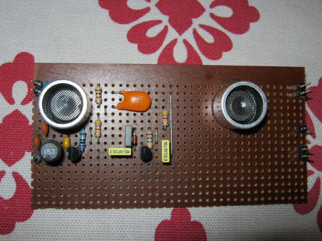
(Note the 15 mH (=153) inductor on the left hand side.)
Before building the transmitter side (on the right of the vertical wire link), I wanted to check that it was working.
Checked the collector voltages:
- a bit too low (Tr2 was 1.9v instead of 2.5v)
- the transistor gain is higher than expected (450 instead of 290)
- easy fix, increase the feedback resistor.
Check the output for noise:
- Less than 1 mV pp (transistor noise) with "impulse" noise at less than 10 mV pp (from the nano providing the 3.3v power?).
Set up a HC-SR04 as a sound source and test the receiver:
- No signal detected?
- Measure the sensor directly and yes the signal is there.
- Check the base of the first transistor - nothing!?
Check for miss-wiring etc., all okay.
Think about it and decide it has to be the inductor:
- Removed the inductor and tested for the presence of a signal - yes the signal is now present.
What went wrong?
Hand calculated the resonance frequency - close enough.
Do ferrites age? Anyway, the inductor cannot be 15 mH.
Checked the DC resistance, less than 0.6 ohm (including the fuse of the multimeter) which is just too low when compared to a 4.7 mH inductor I have (which is about 11 ohm).
Peel the jacket off and count the windings - 22 turns!
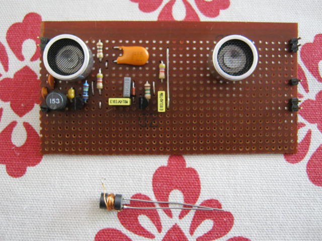
Checked some ferrite datasheets and my estimate is about 15uH not 15mH.
I have been conned!
I have some ferrite beads (FB-43-2401) that with 171 turns of 28 AWG (i.e. ~0.32 mm diameter wire) would make a 15 mH inductor. No, threading 4 to 5 m of fine wire does not sound like much fun. I will have to order some from ebay.
The Sensor Test
Measuring the sensor directly gave voltages in the order of 100-200 mV with the sound source just 10-20 cm away. That is great, the sensor is working as expected BUT is was ringing for 100s of microseconds! Looks like the sensor will need to be damped (properly loaded). In theory, the transistor is matched to the sensor so when powered it should be damped.
Rework the Design Again
Found a toroid ferrite at the local electronics shop:
- 18mm x 10mm x 6 mm L8 material and no other data.
Found a datasheet for L8:
- 1500 ui
- 300kHz max frequency (for ui)
Found a webpage to calculate Al:
- 1.06 uH/t^2
Magic, 120 turns for 15 mH.
Reworked the matching networks for both the receiver and the transmitter and reduced the transmitter choke to 4.7 mH (which I have on hand).
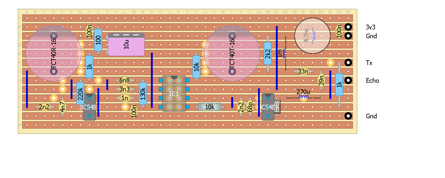
Here is the updated strip-board design:
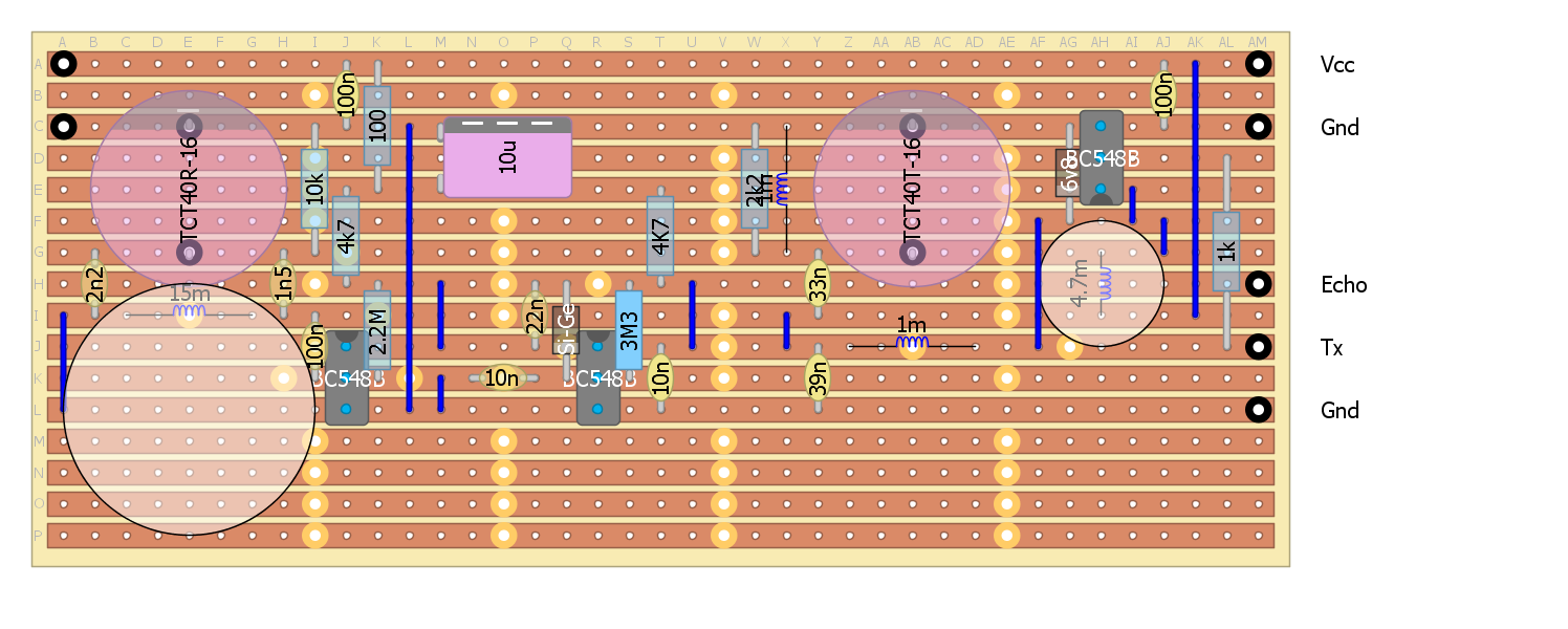 Here is the receiver:
And here is the transmitter:
Damping the Transmitter and receiver Sensors
I am a bit worried about ringing of the transmitter and the receiver sensors.
An unloaded receiver sensor rang for 100-200us when 15 cm away from a HC-SR04.
The matching networks should load the sensors but I have added provision resistors if ringing is still a problem when in-circuit (10k for the receiver sensor and 1k for the transmitter sensor).
Success
I wound the 15 mH inductor last night.
120 turns on a 18mm x 10mm x 6 mm toroid of L8 material.
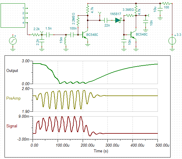
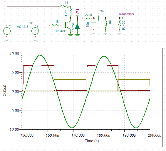
Here is the first stage of the transceiver:
Here is the test set up using a HC-SR04 as a signal source (30 cm away):
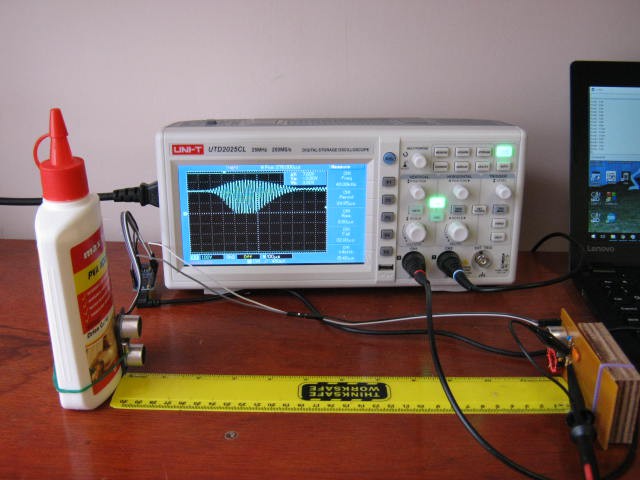
An here is a closeup of the oscilloscope:
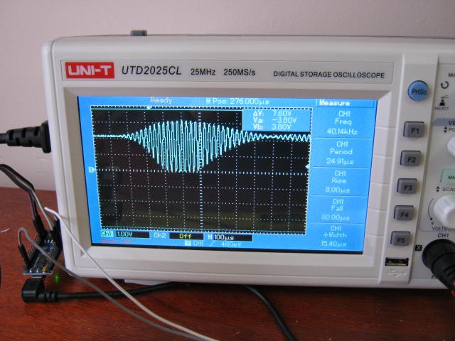
Yes the output is rail to rail! The sensor Q is quite evident with the 300 us ramp up (3 major divisions). Note that the transistor output hits the rails after 200 us. The signal decay is about 400 us.
How strong should the signal be?
For this set up the sensor should (my estimate) produce about 30 mv rms (~100 mv pp).
The display matches the expected transistor performance. based on Tina. So all is good.
I have made provison to further load the sensor to damping the ringings but it is too soon to tell if it is actually required for my application.
Demodulator
Added the next stage (the demodulator), it works but it is not very sensitive or stable.
I think unintended demodulation from the first stage is upsetting the bias of second stage.
I am not sure how I can fix this, at least easily.
Perhaps I should use a 567 tone decoder instead.
Modelling the TCT40RT-16 receiver sensor
I thought it may be of some value to model the receiver sensor.
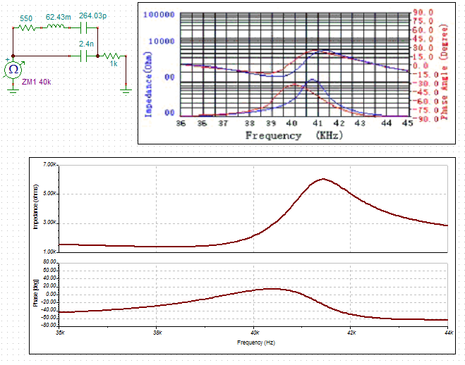
So I measured the parallel and series resonance off the datasheet (39.2 MHz and 41.3 MHz).
The datasheet is not clear which sensor but the parallel capacitance is stated as 2.4 nF.
From the above I calculate 62.43 mH and 264.03 pF for the series components.
The parallel and serial impedances measured off the datasheet are 1.5k and 6k.
I could not get a match for these values by adjusting the series resistance alone so I added a 1k resistance to lift the impedance.
Here is my equivalent circuit:
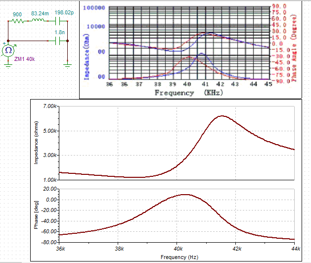
Here is anothe attempt that is closer but without the 1k resistor (I changed Co from 2.4n to 1.8n):
I have had no luck with the transmitter equivalent.
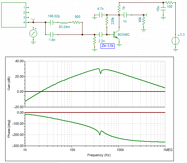
Yet another receiver design
If you are sick of yet another design spare a thought for me!
Anyway, I dropped the input impedance to 3.5k ohm (so I can drop the matching network). I looked at an active filter but lost too much gain:
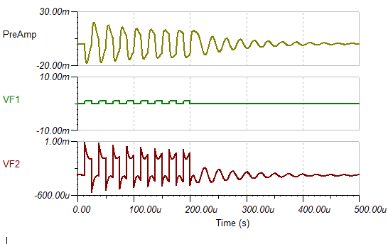
Here is the transient response (at 40kHz):
I designed a 567 tone decoder circuit.
The tone decoder can detect signals down to 25 mv rms (10 mv rms with a 130k pull down resistor on pin 1). The bandwidth at these voltages is small (2-4%) so the decoder oscillator needs to be spot on. The main down side is that "pull in" can take up to 10 cycles (250 uS). Recovery time would be similar.
Here is the board layout:
Here is the assembled board:
I have had to migrate back to 5v as the LM567 does not work at 3.3v.
No problem for the transmitter (3.3v drive is okay).
The Echo will however be 5v, but as it is feed though a 10k resistor this will not hurt a 3.3v MPU (but about 100uA will flow through the protection diodes).
I have not tested the transmitter yet - tomorrow
The receiver works
It picks up the initial transmit pulse and a reflection or two depending on the sensor orientation.
There is almost a continuous ringing/noise of about 5 to 10 mv pp (just below the LM567 detection threshold). Very similar to the transient response above.
I will have to experiment with damping the sensor with a load resistor.
AlanX
Discussions
Become a Hackaday.io Member
Create an account to leave a comment. Already have an account? Log In.
Hi K,
>>Which schematic you are looking at? Is it mine on githbub? Or the mark up one? >>Remember that a few versions of it was the original reverse engineered schematic f?>>from China that uses 20kHz.
It was not meant as a flame(?).
The annotated circuit was fine. The only comment is that the recommend gain-bandwidth for active filters is GWB>10*Gain*Freq., but if you don't really care about the filter shape then it will not matter and for your application that is probably true.
It was the one in the link (https://hackaday.io/project/5903-sonar-for-the-visually-impaired/log/19976-ultrasonic-module-hacking). Okay, I did not realise the hack was of a 20 kHz system.
Anyway, I built the first stage of the receiver and it works quite well (within design expectations). The sensor Q is evident so I may need to damp it but I don't know if it matters yet.
I added the second stage, it works but not very well, I think I have a problem with demodulation from the first stage upsetting the second stage bias, reducing sensitivity and generally messing it up.
Have to have a think about how to fix this but I am leaning towards a tone decoder.
Regards AlanX
Are you sure? yes | no
Hi K,
I saw your transmitter spice model but not the receiver model.
Based on your transmitter model I reworked the transmitter matching network down from 500 ohm to 400 ohm a few day ago. Reworked the network last night trading off output power for a flat response and no ringing, between 320 to 500 ohms (to be safe).
I found a reference to "Resonant Mode Converter Topologies" that explains the unexpected power boost I got when I added the zener to the transmitter circuit.
I built a model a while back for a different transmitter/receiver pair. I have rebuilt my computer since then so it was lost.
Providing I have not pushed the matching networks too far then they should properly load the sensors (cross my fingers!).
Optimal Response Time
For your receiver based on the datasheet (i.e. 2k2 impedance at 40kHz), the input resistor should have been about 2k2 for proper loading, that is for maximum power transfer (rather than 10k). That is probably why the 22k shunt improved things, but at the cost of sensitivity. The negative input of an op-amp with feed-back is a virtual ground.
Now I am assuming a properly matched network (for maximum power transfer) results in an optimal response time which sounds right but may not be actually true.
AlanX
Are you sure? yes | no
Maximum power does not mean maximum voltage output. Actually 4.7K works better, but I need the range. Since I can dynamically define my thresholds for the envelope, there are tradeoffs I can do. i.e. limiting how close a distance I can detect (limit by ring) and how far (sensitivity)
When I say ringing in my receiver I mean the mechanical wave travelling through the PCB before the first echo. I think I have show the before and after picture in the log very clearly to what the resistor does and what I am trying to solve.
You are talking about something entirely different. Not sure what you are trying to solve.
The extra electrical loading increase the losses and lower the Q factor. So damps out the initial vibration faster.
From what I have seen ages ago opening a transducer, the receivers have a piece of tape glued on the disc inside for a lower Q value. This help to get a wider bandwidth. The transmitter has a higher Q value for higher outputs.
http://traktoria.org/files/sonar/transducer/simple_transducer_intro.pdf
Are you sure? yes | no
Hi K,
My ringing is of the sensor from the HC-SR04 that is about 15 cm way rather than mechanical transmission from the transmitter (I have not fired up the transmitter yet).
I am pretty sure my ringing is simply because the sensor is unloaded when the transistor power is turned off. Otherwise these sensor would have little chance of working in practice.
Maximum power transfer should mean minimum amount of ringing, it has a slow roll off so 4k7 should be a good compromise for voltage gain and damping.
As receiver noise is not really a problem you have other options. Increase the gain (an op-amp with greater bandwidth than the 324). But then you may need to vary the gain with time due to mechanical noise. This is probably the reason behind the variable gain of the HC-SR04 (mechanical noise).
In my setup I can receive multiple echos (recovery time is less than 200 us or 3 cm one way). So I can use a window instead of variable gain.
** Looking at your schematic again **
From memory the rule of thumb for an op amp is GBW>Freq*Gain and for a op amp filter GBW>10*Freq*Gain.
From your post the LMV324 has a GBW of 1 MHz. So your are okay with your preamp (x6.2).
For the filter I calculated 20 kHz(?!) with a gain of 6.
Now you are breaking the rules, even at 20 kHz.
I did a manual check and the centre frequency is still 20 kHz!?
The overall circuit will still work as the filter gain at 40 kHz is just less than 1 (range will suffer though).
Worth a check but I make these silly mistakes myself (increases with age!).
Post Script
Thinking about the op-amp filter GBW rule (which is for a maximum 10% gain error), the errors probably do not matter in this application.
AlanX
Are you sure? yes | no
Which schematic you are looking at? Is it mine on githbub? Or the mark up one? Remember that a few versions of it was the original reverse engineered schematic from China that uses 20kHz.
>So the big question are there any improvements in the current rev. of the module?
(Chinese module)
>A couple of the resistor values was change around the bandpass filter of the current version of the modules, but the filter center frequency is still about 1/2 of it should have been.
Mine uses a much higher gain to compensate for the 3.3V transducer. My logs are definitely very explicit. I am not the kind that lack details.
How do you explain this from my log? That doesn't look like a 20kHz.
>Here is the frequency response plot with the 2 resistor values change that Emil suggested to move the frequency to 40kHz. Not sure if that's already been incorporated into the new modules.
More on what I said on my log:
>According to LTSpice for the gain at output of U2C at 40kHz
>LTSpice seems to be having some convergence issues with U2B in the model. U2B gain is 7.5X (17.5dB)
>With values as show: overall gain = 11.8dB
>With R3 = 1.5K, R5 = 22K: gain = 32dB (this corrected for the wrong 19kHz filter frequency. It is now at 39.26kHz)
------------- !!!!!!!!!!
>I boost the gain by changing R2 = 220K: gain = 43.54dB
>I have to compensate for the reduced transmit power (3.3V vs 5V), so I increased the gain by 3.5X (11dB).
>I ran the AVR at 3.3V, so the transmitter is driven at about 6.6Vpp vs the 10Vpp at 5V input.
Seems like you are not reading correctly. Not sure if you have an actual problem about your ring. I have seen no scope pictures posted neither.
Are you sure? yes | no
Hi K,
The ringing was when I tested the receiver (with no power so unloaded) with a HC-SR04 about 15 cm away. It went on for 100-200 us! I don't think it was mechanical vibration.
As you used a 22k resistor it would seem than unless the transistor presents a proper loading (it should when powered), then a back-up resistor directly across the sensor is a fall-back position.
I note that the test setup for the 400RT160 they load it with a 3k9 resistor (and the sensor impedance is that). I remember some discussion in a paper about loading/sensitivity/spurious response that suggests they should have some loading (10-20k from memory). I think that sensor was about 20k anyway.
Okay, I have talked myself into provision of a loading resistor on both the transmit and receive sensors, just in case.
AlanX
Are you sure? yes | no
My front end essentially has a 10nF and 10K (C7, R8) AC load due to feedback. Opamp circuits are simple that way.
The 22K resistor is an additional load for the transducer for the left side.
My transmit sensor is shorted - essentially with 20-30 ohms of driver impedance driving both terminals to ground after the first 8 pulses. That was the only way to electrically damp the ringing from the transmitter. If I let these pins float, the amplitude would start itself up again. (far right on top trace)
All mentioned in here:
https://hackaday.io/project/5903-sonar-for-the-visually-impaired/log/19976-ultrasonic-module-hacking
Like I said previously, this behaviour is predicted by the Spice model I used.
Are you sure? yes | no
Hi K,
I check this schematic as well and the fc is okay (~44 kHz).A GBW of 880 kHz for pre-amp and 320k Hz for the MFB filter is push it.
AlanX
Are you sure? yes | no
Hi K,
Yes I think that is the way to go.
I found some unmaked toroids at the local electronics store.
They are 18mm x 10mm x 6mm and L8 material.
I found a reference to L8:
o ui=1500
o max frequency 100 kHz.
I found a webpage with a calculator and the Al was 1.06 uH/t^2.
So 120 turns will give me 15 mH.
The hole is four times the area of my ferrite beads so much easier to wind.
But I will have to rework the strip-board layout.
These (receiver) sensors ring like a bell when unloaded.
Did you load yours with a resistor?
AlanX
Are you sure? yes | no
Only on one of the channels - left side PCB as it is not mounted on the main board so there are a lot less damping. The right side is mounted more rigidly and has been worked into the threshold profile. :)
https://hackaday.io/project/5903-sonar-for-the-visually-impaired/log/25290-firmware-progress-2-acoustics-mechanical
I ended up using a 22K resistor in my case as a trade-off of range vs damping.
Have you consider mounting one of the transducer on foam to mechanically isolate it?
Are you sure? yes | no
You can make a substitute inductor by raiding your junk box until real parts arrive. AC Common mode filters are around 500uH to 1mH range.
The core is such that much fewer turns to get high inductance. Inductance is proportional to N^2 so it would only need 4x turns to get close to 16mH.
Are you sure? yes | no