 Clara Hobbs
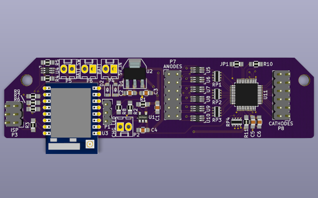
An LED traffic signal, converted to a battery-powered, LED matrix controlled by an ESP8266. The controller is derived from an Adafruit Feather HUZZAH, but generally allowing higher currents, and with no built-in USB-to-UART chip. The LED matrix is driven by an STP24DP05 constant-current LED driver. The ESP8266 runs MicroPython, allowing easy development and testing.
0%
0%
Traffic Signal LED Matrix Display
A networked LED matrix display made from a surplus LED traffic signal
Become a Hackaday.io member
Already have an account? Log in.
Just one more thing
To make the experience fit your profile, pick a username and tell us what interests you.
Pick an awesome username
hackaday.io/
Your profile's URL: hackaday.io/username. Max 25 alphanumeric characters.
Pick a few interests
Projects that share your interests
People that share your interests


 Anool Mahidharia
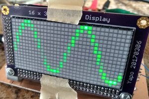
 Ted Yapo
 OK Design
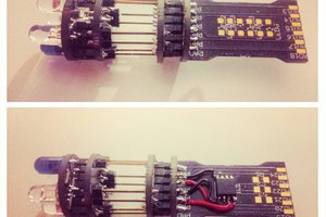
 davedarko