 Clara Hobbs
The North Carolina State Surplus Property Agency warehouse in Raleigh usually has several huge bins full of LED traffic lights for sale for $3 each. With each light containing over a hundred LEDs, that's a fantastically low price for the LEDs alone. The cheapest green LEDs I can find at Mouser still cost more per diode at quantity 5000 than these surplus traffic lights. The only problem was that I had no use for a hundred or so LEDs, so I went home empty-handed. A couple weeks later, I finally came up with a use for one of those traffic lights: re-wiring it as an LED matrix. Two trips to the surplus property warehouse later (the first light had some bad LEDs, so I went back to get a second one to replace the bad ones, only to find that the second one didn't have any bad LEDs), I set to work.
After opening the good traffic light, I cut nearly all the traces on the LED circuit board. Then I wired the anodes in rows and the cathodes in columns, joining the first and last row and column together to shrink the matrix from 13×13 to 12×12. Saving pins in this way seemed like a good idea, even though at this point I had no concrete plans on how to actually drive this matrix. The traffic light sat in this condition for a couple months with no further progress.
Then, one day I saw the ESP8266 MicroPython Contest, and thought it seemed like the perfect excuse to finish the traffic signal LED matrix. I looked at available ESP8266 modules, and thought the Adafruit Feather HUZZAH seemed like a good choice. Then I looked at it in more detail and started seeing where things would go wrong. Its voltage regulator could only supply 600 mA, which isn't a comfortably large amount for running an ESP8266 and my LED matrix. Also, while the battery charging seemed nice, I didn't like that it was charging from USB, and could only charge with 100 mA (unless I changed a resistor and figured out how to ask the host if drawing 500 mA is okay). I wanted to use a 2500 mAh battery so I could run the system for several hours on a single charge, and having to charge it for a whole day didn't sound very good. I also wanted an external antenna, which the ESP-12 module doesn't allow.
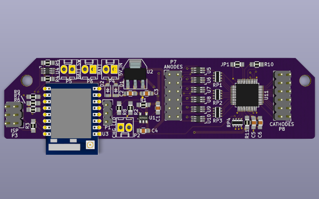
I decided to make my own board based on the Feather HUZZAH, but fixing its shortcomings for this particular application. I used a 1A voltage regulator, a barrel jack for power, and a UART header for programming rather than an on-board USB-to-UART chip (sorry about the weird pinout, it matches some other boards I already had). The battery charger is the same as the one on the Feather HUZZAH, but configured for 500 mA charging current. I also used an ESP-07 module so I could use an external antenna. After some research, I found the STP24DP05 LED driver chip. Using some external PNP transistors, it allows me to drive the whole matrix at a constant 20 mA per LED. I made the board with KiCad, ordered the parts from Mouser and the boards from OSH Park, and in a couple weeks I put it together. Much to my surprise, there were no mistakes in the board despite how many parts I had to hand-copy from datasheets into KiCad.
I finished building the board Monday afternoon, and I've been hacking the software since then. MicroPython makes the development pretty easy, but it's not really capable of driving the display as fast as I'd like. It works pretty well at 41 ⅔ Hz, but it's noticeably "flashy". I've written code to load PBM images, which are perfect for this kind of display because the files are tiny, they have just 1 bit per pixel, and I can draw them with The GIMP. I'll write more about the software I've written for it in the next post.
Discussions
Become a Hackaday.io Member
Create an account to leave a comment. Already have an account? Log In.