 i.abdalkader
USB: The camera is USB powered, there are lots of app notes on USB interfacing to read, but here are some tips that I've learned: match the deferential pair, use terminations(1) , use a ferrite bead on VBUS, limit the inrush current and limit the current to 100mA before negotiating power with the host (see FTDI Hardware Design Guidelines app note)
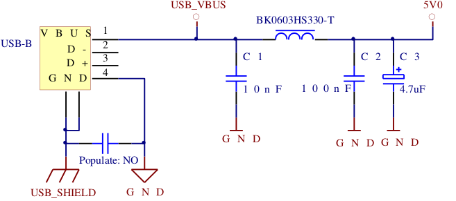
The USB 2.0 specs requires limiting the inrush current to an equivalent 10uF capacitance, and since there's no PM chip (on the small camera board) I needed a triple regulator with an internal soft-start to save components and board space...
After some searching I found a triple ADP regulator (3.3/2.5/1.2) which fits nicely, but I also found out that the sensor has an internal regulator for the core supply (that can be controlled in SW) so basically I only needed 2.5v/3.3v, finally, I used the ADP222 (3.3v/2.5v) 300ma in addition to the internal soft-start, it costs less than 2 separate LDOs, wastes less power and has better heat dissipation.
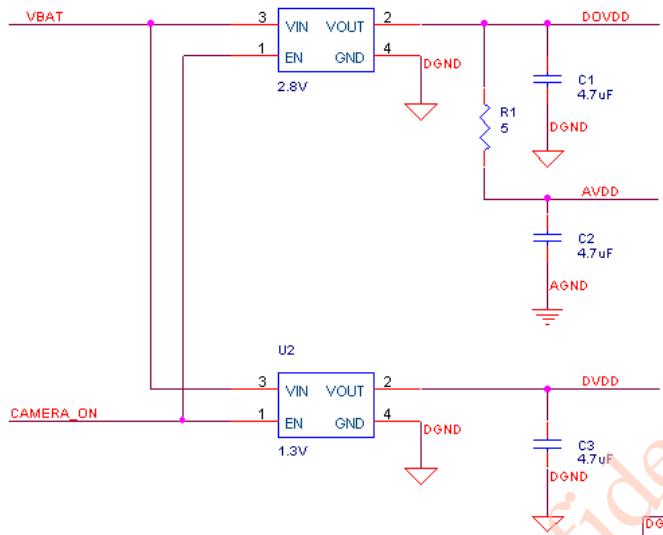
Sensor: The sensor needs 3 different supplies, core, digital and analog, the analog supply can be connected to the digital supply through a filter, which takes care of that, and the core is supplied via the internal regulator, so it basically boils down to a single 2.5-2.8v supply, this is from an OV HW app note:
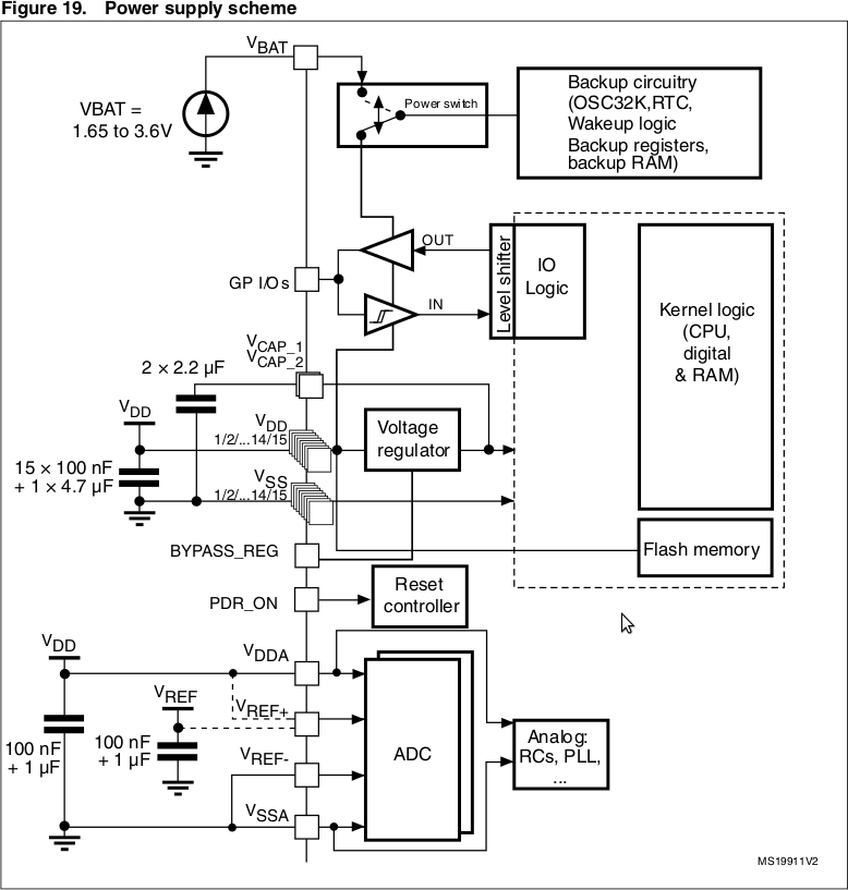
STM: The STM is powered from the main supply (3.3v) it works at a lower voltages, but that will limit the speed (and other things). I followed the recommended power supply scheme in the STM datasheet, each VDD pin gets a 0.1uF cap, plus one or two 10uf, caps for VDDA and 2 more caps (2.2uF) for the internal regulator:
SD Card: The uSD is decoupled with a 0.1uF and 22uF (or more), more importantly, all pins that can float are pulled-up.
(1) The STM32F429 has internal terminations in the driver, so no termination is needed.
Discussions
Become a Hackaday.io Member
Create an account to leave a comment. Already have an account? Log In.