 Dan Julio
Nest has redefined the game of controlling a house's HVAC system - at the expense of all one's data going through a company that loves to collect personalized data about people and with no promise that at some time in the future the device will no longer be supported. Several of my friends have Nest thermostats and I talked with them about what they liked and didn't like. I came away from the conversation thinking that the most sophisticated aspects of that device are unnecessary for most people but I wanted to try to reproduce some of the features in my own system.
First and foremost, however, I wanted to implement a safe system. My house is very simple from an HVAC perspective. Only a hot water boiler with two zones and no air conditioning. I decided to leave the existing boiler controller in place and have it see my system as a simulated thermostat. The components of my system would act as a thermostat on their own without any dependence on the greater home automation system. The final architecture was three devices. Two replacement thermostats and an interface board that went next to the boiler with relays that simulated the output of a traditional thermostat.
I didn't want to replace any wiring which was deeply embedded in the house so settled on using the two conductors to supply DC power to the thermostats from the interface board. The thermostats then couple in a high frequency AC signal that is decoded using an LM567 analog tone decoder to drive the relays on the interface board when they call for heat. The only micro-controllers that have to work for the boiler to work are in the thermostats. There is no dependence on radio packets to call for heat. The interface board also contains a micro-controller that is tasked with watching the relays and measuring the temperature of the boiler room. Its code acts as a safety feature and it has a master "off" capability in the case where it thinks the boiler is malfunctioning (for example the thermostats call for heat but the boiler never seems to run). It can generate fault packets to the central controller.
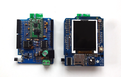
Since this was a big unknown project for me, it ended up happening in stages and all the boards were hand wired. They used an Arduino LCD shield from Adafruit and a NRF24LE1 module from diyembedded.com. I added a new set of commands to the QualColor protocol to support HVAC functionality. Existing commands for provisioning and configuring the LED controllers were also applicable to these new controllers.
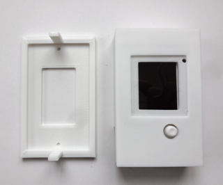
3D-printed plastic enclosure including button nipple for 5-way joystick.
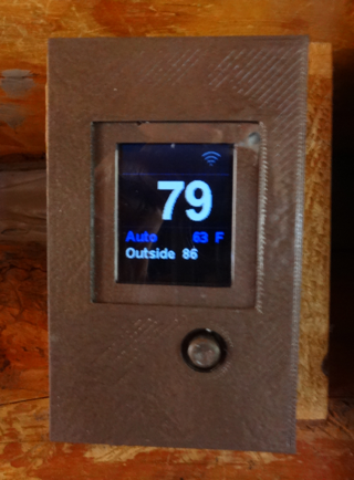
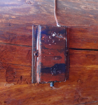
The downstairs thermostat got painted to match the decor...
Each thermostat is fairly stupid and has three basic modes of operation:
- Automatic where an external controller configures the temperature set-point.
- Manual, entered with a short press of the joystick, where the user can adjust the set-point by toggling the joystick up or down. Each night at midnight the external controller commands the thermostats back to Automatic operation.
- Burst, entered with a long press of the joystick, that simply turns the boiler on for a short, configurable time for a quick bit of heat. Initially the burst period is 10 minutes but using the joystick it can be increased or decreased in units of 5 minutes up to two hours.
The large display is the current temperature (since I think this is the biggest daily use of a thermostat - to see how hot it is). Under it is the mode and current set-point (or remaining burst time). Below that is a line that can be set by an external controller. Currently I alternate the date and outside temperature. Above temperature is a set of icons that indicate the thermostat is calling for heat (flame icon), is in configuration mode (wrench icon) or communicating (radio bar icon). One final line of text is displayed when the user performs certain configuration actions (such as store a new default manual set-point). The thermostat also has a provisioning mode to allow an external device to configure it. A photocell controls the brightness of the LCD backlight so it dims at night. An LM36 analog temperature sensor is used along with a set of calibration values stored in EEPROM.
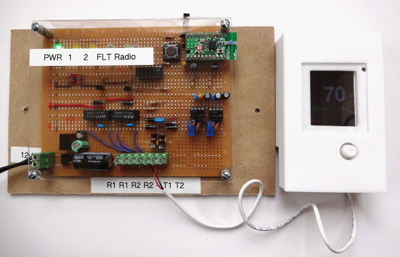
Interface board connected to one thermostat during testing.
There are also two temperature-only sensors, one outside and one in the crawl-space under the house. They were built using a hacked nRF24LE1 LED controller board with new code and use the same LM36 and temperature monitor commands as the thermostats.
The main control program currently maintains a timed set of set-points that are switched between summer and winter. For example the house is kept colder overnight, warmer in the morning, less warm during the day and then warmer again near dinner. This works pretty well but over the long haul, I plan to make two additions to this system. First I plan to replace the temperature-only sensors with a larger set of environmental sensors that monitor temperature, light levels, humidity and motion. Modify the main control program to understand activity in the house to augment the timed set-points. The additional sensors will also be used to automatically control certain lighting. Their PCBs have been designed but firmware is still incomplete.
I consider this HVAC system to be a prototype and have ideas of how to extend it for air-conditioning control as well as different furnace controllers and types.
Discussions
Become a Hackaday.io Member
Create an account to leave a comment. Already have an account? Log In.