 Dan Julio
Over the years I designed additional prototype controllers and drivers. As I mentioned earlier, the QualColor protocol is packet and command based (for example, as opposed to streams of intensity values used by WS2812 LEDs). Packets are small, 16 bytes or less and grouped by function type. There are provisioning packets that all devices interpret like SetAddress or SetRfAddress. Device-specific configuration packets (for example packets to set configuration or calibration data that are device dependent). Light commands such as SetHSVcolor that sets a color value immediately or FadeHSVcolor that fades to a new color value over a specified period of time. Information and Error report packets (for example an over-temperature Fault condition reported by a light controller). HVAC commands to read temperature values and configure set-points. One of the primary architecture goals was to make a distributed system so that any one control device wouldn't have to know anything about the devices it was controlling. The original handheld touch color remote control can control one or a million fixtures. It can also control a fixture with a controller designed long after it. One requirement of the protocol is that packets are visible to all devices. This puts an upper limit on the number of changes that can occur at a time but I tried to design a reasonable goal for a lighting and home control architecture. The wireless links can support (with repeated packets) about 100 packets/sec. The wired links can support a higher rate.
I chose the HSV color space because it allowed me to separate color specification from implementation. Over time I have supported dimmable white, dimmable and non-dimmable white, RGB, RGBA and RGBW implementations. Each controller is responsible for mapping HSV to its specific implementation. HSV also allows neat tricks like fading to a color 180 degrees around the color circle from the current color which is useful when making didactic or tridactic color patterns with multiple fixtures without having to know what the current color is (for example it has been randomly chosen at some previous point). The HSV control packets also include a set of flags that allow control devices to only change some of the HSV components, or to apply them as a delta to the current values (the button remote in the kitchen uses this function so that each press of a set of buttons increases or decreases the current intensity of one fixture by a few percent).
Because I had controllers that worked both wirelessly and via the wired connection, I separated control functionality from driver functionality on a set of boards sized to fit in single-gang switch enclosures. For example either the wired or wireless controller board can connect to one of 4 different LED driver boards via an 8-pin flat cable.
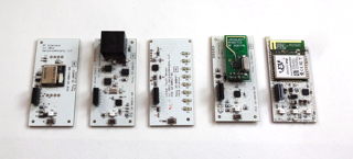
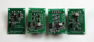
LED Driver Back Boards (left to right): Single channel (white) switch-mode constant current driver, 4-channel constant voltage driver (e.g. for RGB or RGBW strips), 4-channel constant current driver (e.g. for RGB or RGBW HB LEDs), Single channel constant voltage driver (e.g. for a large number of white LED strips). These drivers can connect to either the wired or wireless LED controller. The single channel devices can also connect to the linear touch dimmer to make a more traditional dimmer for LEDs without any remote control.
The direct-wired version of the protocol is called QualColor Link. QualColor Link is a simple bi-directional serial link running at 57600 baud and is carried on RS422 compatible differential signals along with 4 12VDC power lines in standard Cat-5 cabling. The packets are encoded with a checksum and it supports in-band flow-control. There are three device types
- Control : Touch dimmer or RF interface to connect to the wireless system. Takes power from the cable.
- Endpoint : LED or other controller. Self-powered with a provision to back-power a control device.
- Link Series Device : A special type of LED controller where packet data is passed from unit to unit and all units share the same zone address.
There is also a hub that automatically configures based on the type of connected device.
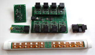
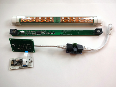
QualColor Link Devices: Interface (connects to LED controller or RF Interface), USB Host interface, 8-channel Hub with power distribution, Link Series RGBW fixture and Link Series Power Injector.
Link Series devices started with the idea of a smart "Pixel" that was a single 5050 RGB LED and small micro-controller that used a variant of the wired protocol with extensions for enumeration. The idea is a set of devices connected to each other in a serial fashion with the interconnect providing power and data. I used it for costumes initially. Link Series devices always have sequential Unit addresses in the same Zone.
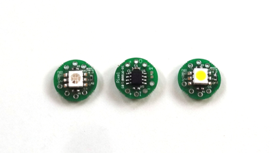
RGB and White Pixels. +5V power supply and serial connection between boards. Packets are repeated from device to device unless in the special enumeration mode where and address is incremented as it is passed from device to device.
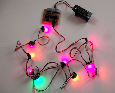
Costume Pixels with a handbuilt arduino controller and 5V battery supply. One cool feature was the inclusion of a photocell on the arduino board which can dynamically adjust the brightness of the pixels to match the environment using the "V" component of the HSV commands without affecting the random programs that set the fade colors of each pixel or group of pixels.
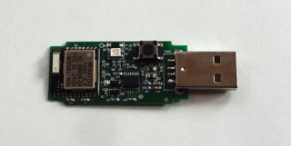
A nRF24LE1 module made for a small USB dongle providing a wireless interface into the QualColor system for a host computer.
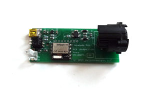
The nRF24LE1 was also a good fit for a simplified DMX controller allowing any white or color-wash DMX fixture to be controlled wirelessly.
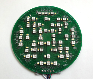
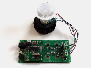
Before RGB strips became ridiculously cheap I designed a custom RGBW PCB with a layout for good light diffusion.
Discussions
Become a Hackaday.io Member
Create an account to leave a comment. Already have an account? Log In.