 Ted Yapo
It's funny how a few days after you "finish" a project, you realize all the mistakes you made. Since I've started documenting projects as I go, you, dear reader, get to watch me stumble :-)
I realized last night why the serial adapter cable supplied with the meter is made the way it is, and how to get my original PC-only code to work correctly, so this adapter is not strictly necessary to operate these meters for programmed measurement. But, you still need a USB-to-serial adapter, and I thought of an enhancement for this design that I still think makes it worth using.
Flow Control
First, here's the diagram of the meter cable again. For the moment, ignore the right side of the figure.
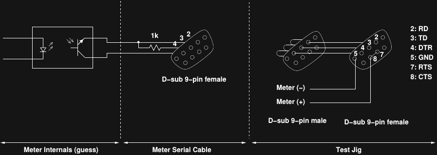
The meter has an opto-isolator inside that "shorts" the two wires going into the serial cable shell to pull the RD line up to a logical zero (crazy RS232 inverted levels). When the isolator is off, the RD line is pulled down to a logical one by a 1k resistor to the TD line, which is not used for data within the meter's protocol. This is a neat trick in that it preserves isolation between the meter and the serial port, but as I realize now, it's actually more than that. If you de-assert DTR, the data stops flowing. It might stop in the middle of a character, but when you start it back up, the receiver will regain sync on the next 14-byte packet. Using this, PC-based code can prevent buffering issues by only asserting DTR to take a measurement, then de-asserting again to stop the flow.
I'll have to go back to the description and other logs and edit the places where I said it was impossible to ensure correct data without some kind of adapter, because it's certainly possible, and not even very difficult.
Testing the idea
So, this brings us to the right side of the figure. I think with a simple test jig, the original buffering problem can be replicated, and the software-only fix tested. Here's a picture of the assembled test jig, which sits in between the meter cable and a USB-to-serial adapter:
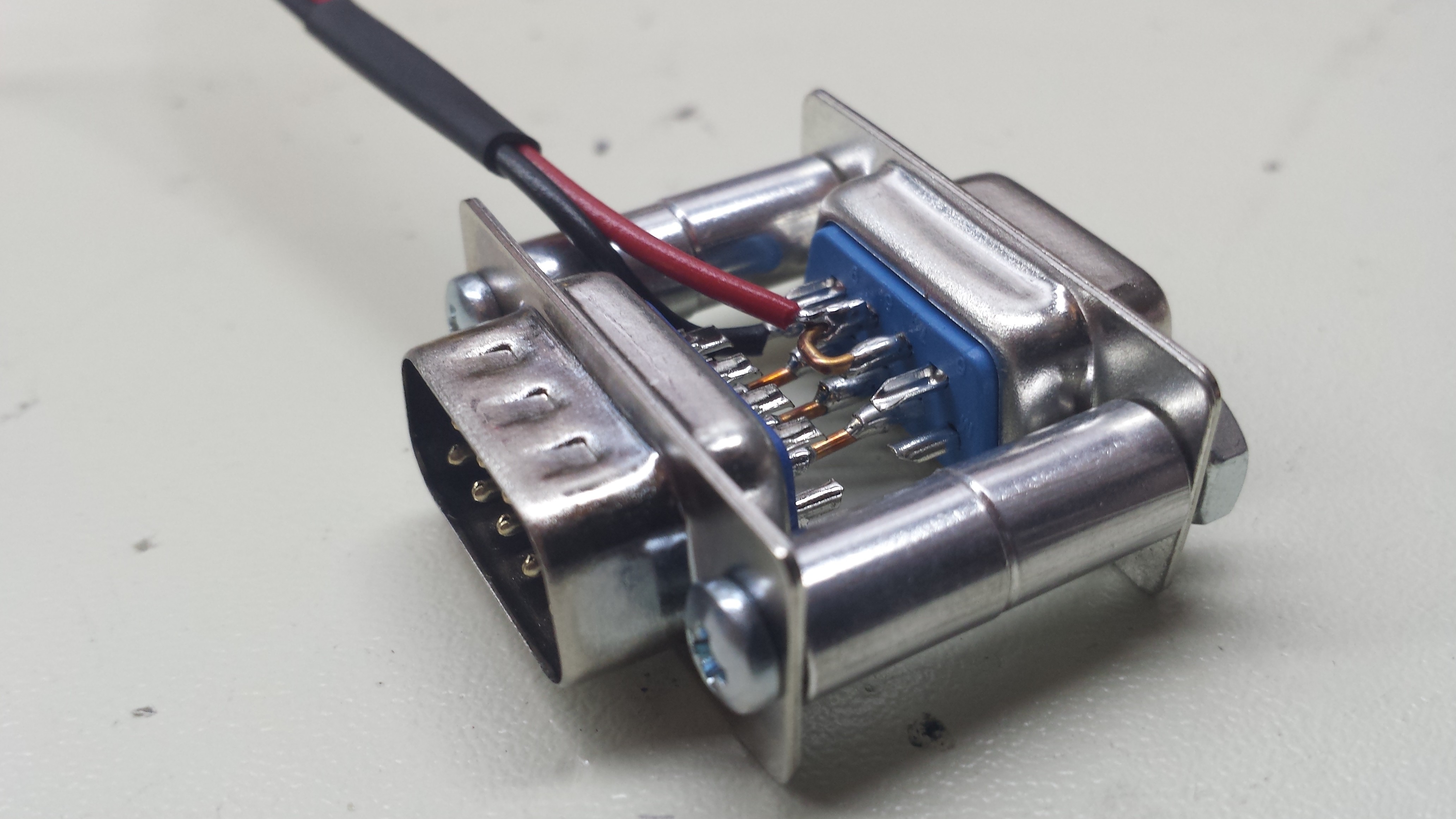
As shown in the schematic, the RD, TD, and DTR lines are pass-through so the meter works as usual. The RTS and CTS line are connected as a loop-back, so that code on the PC can assert RTS, then know when the line has actually been asserted by reading CTS. The RTS line and signal ground are connected to the meter's inputs on the "voltage" setting. To test PC-only code reading the meter, you can do the following:
- set RTS either asserted/de-asserted
- poll CTS until it shows that RTS has actually been set
- read the meter using a candidate protocol
- check if the meter voltage reading reflects the known state of RTS (i.e., did we get stale data?)
I ordered another meter for longer-term testing (and general use, since I typically have the first two in a dedicated testing setup for the forseeable future). When it comes later in the week, I can try this out. I'll put the PC-based C++ meter reading code in the GitHub repo, too.
Device Enumeration
So, what can the adapter do? Obviously, translation from LCD-segment maps to human-readable ASCII is still convenient to have in the adapter rather than on the PC side. You also need some kind of USB adapter to use these meters with a PC, too, and the adapter fits that role well. I think there's another enhancement that makes sense. One of the problems with many USB-to-serial adapters is that they end up mapped to different devices (linux) or ports (Windows) depending on when/where you plug them in. For tests with multiple meters (I'm currently using two of them), this is a real pain: each time you re-arrange the test setup, you need to check which device the meters came up as. Although some USB-to-serial bridge chips have a user-settable serial number which can be used to correctly map each port as it is connected, many (including the ones I have) do not. So, adding a mapping/discovery protocol to the adapter would make it pretty useful.
Since the CH340 bridge used in many cheap arduino nano clones doesn't have a settable serial number, a discovery protocol has to be used over the serial port itself. My approach will be to have the linux udev system map aliases for detected CH340's to devices of the form "/dev/ttyCH340_X" with X being "0", "1", etc. Software on each adapter will respond to the new 's' command to return a string of the form "METER-ADAPTER-NNNN" with "NNNN" being a unique serial number. A program using the meter(s) can then call a python library which will scan through the CH340 devices and enumerate all the attached adapters.
Over-Range Indication
The meters are auto-ranging, but on current settings, they need to be manually set to uA, mA, or A ranges. Exceeding the current on any particular range produces an "0.L" display on the meter, which the adapter doesn't currently decode. I'll add that as an enhancement, too.
Discussions
Become a Hackaday.io Member
Create an account to leave a comment. Already have an account? Log In.