 bram
bramFor the remote rotary encoder I use a spare board that I designed for another project. The board has the size of a normal flash drive and on board are: a ESP8266-03, a 3.3v regulator and a capacitor. And there are a few connections broken out: 2x GPIO, UART, Bootloader button and a second pair of power connections.
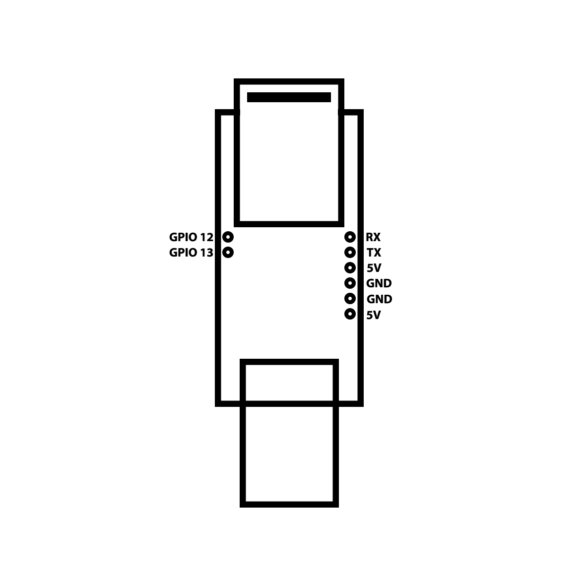 This board is perfect for this project because every necessary connection is available. On board is a bootloader button but I connected another button to is so I could access it without opening the case. The rotary encoder used in this project is a simple breakout from china like this one and is easy to wire up. It has 5 pins:
- CLK --- Clock
- DT --- Data
- SW --- Switch (On my module I had to solder on a 10k resistor)
- VCC --- Power
- GND --- Ground
Wiring:
- GPIO 12 --- CLK
- GPIO 13 --- DT
- SW --- Not connected
- VCC --- 5v
- GND --- GND
Discussions
Become a Hackaday.io Member
Create an account to leave a comment. Already have an account? Log In.