 Pamungkas Sumasta
It is going to be in Altium, yes Altium Designer. I repeat Altium, not Eagle sorry.
I've had enough amazing time using Eagle for more than 6 years since 2009. only until the beginning of 2016 I started to use Altium Designer as my current job mandates. And you know what? I felt like my whole life in designing PCB prior to using Altium Designer seems more like a lie. The easy way to put this is just like when you always use Paint to adjust and modify some image and in all the sudden someone introduce you about Photoshop. But well, I do agree that the learning curve is a bit steep with Altium, but I had to say it was worth the time.
I do also understand that Eagle is nowadays a common tools within Maker Community, so using tools other than Eagle might give some disadvantage for many. Either way, I was simply just cannot move away from using Altium at this stage, especially considering the limited time that I had etc. Also in the future I will try to see if I can properly export the Altium design files to CircuitMaker. which is a strip-down version of Altium Designer that is free and online/community based.
Schematic Section
During the design process I separated the design into three different schematic schematic sheet. Not just for readability, but also one of the sheet was a import from my previous project. So well, there is no reason not to do it.
Cherry MX Matrix switches
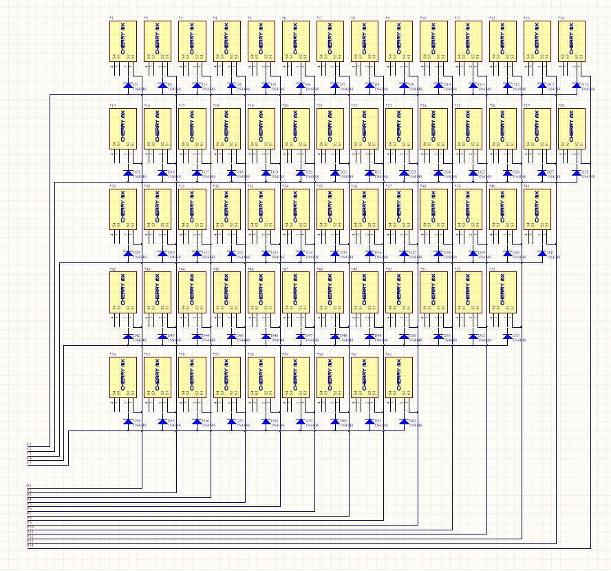
First and foremost is the Matrix of Cherry MX switches. It is fairly straight-forward, just an array of 14x5 switches connected directly to the pin of the Microcontroller. Though you see a diode on the schematic below, in the end I decided to replace it with just a resistor. Because the potential crosstalk between switches can be handled inside the software by setting the irrelevant pin to high impedance in every scanning iteration. So no diode is really necessary.
Another thing to note also you might find the last row (R14) to be unnecessary. The two switches can be hooked up to Column five (C5) and that way you can save one pin from the Microcontroller. But well, I didn't do it. simply i was trying to avoid un-uniform-ity in the routing. If you take a closer look, the number of switches per column in the schematic is identical with the number of switches per column on the board layout that we'll discuss in the next Project logs. I thought it could ease the mapping process in the software in latter stage.
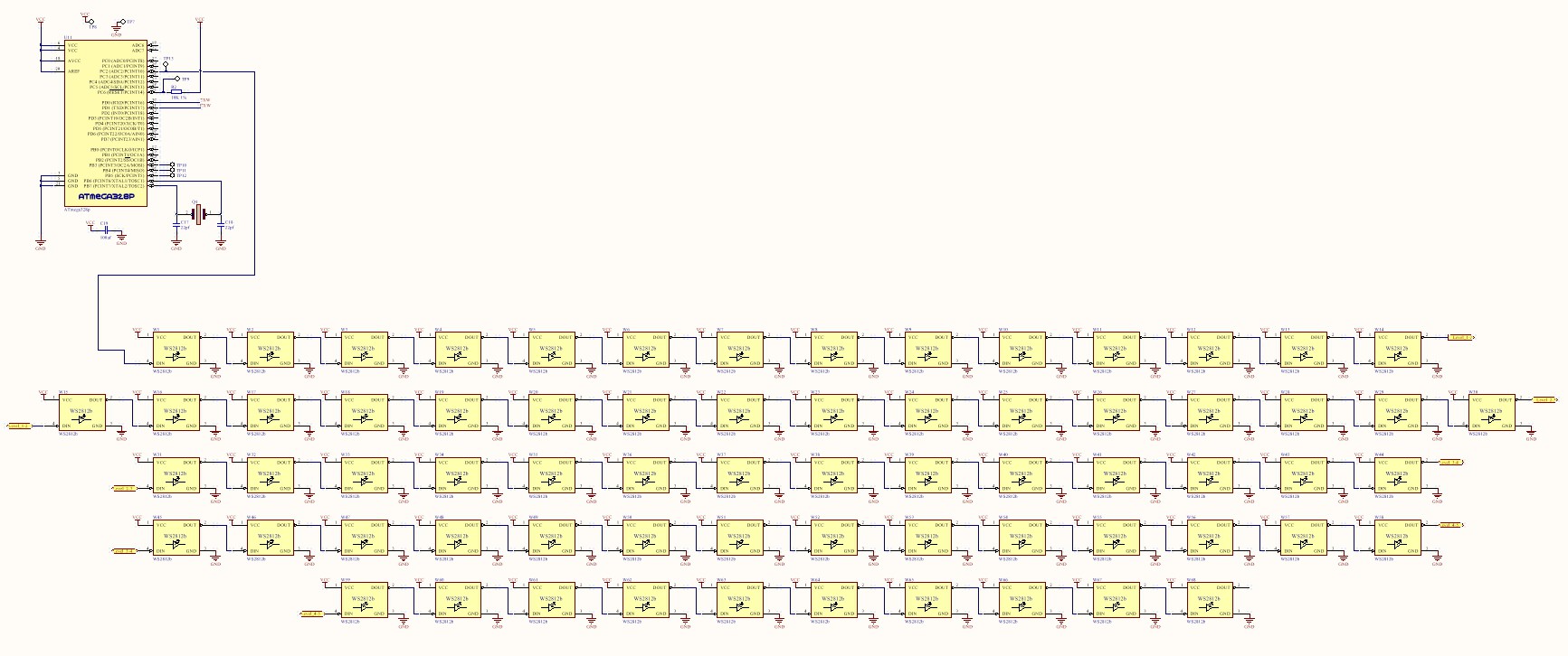
Next thing to discuss is the array of the WS2812b RGB Led, the one and only favorite. Exactly 68 pieces of those were used to nicely fill the gap between the switches. As you might have known, the beauty of this LED is that you only need one microcontroller pin to sequentially control hundreds or even thousands of this LED. So schematic wise, it was not that difficult. But as I briefly mentioned in previous project log, I might actually need a co-processor to control the LED smoothly without being interrupted to much with other primary routine. Hence, in the schematic below you see an Atmega328p microcontroller as well.
Primary peripherals
Well, following the above, it is now time to get into more serious stuff. The primary controller and the peripherals itself. The schematic provided below depicts in great detail the complete wiring diagram of the system. All the standard communication bus are occupied although there are still some free pins for additional features in the next design iteration.
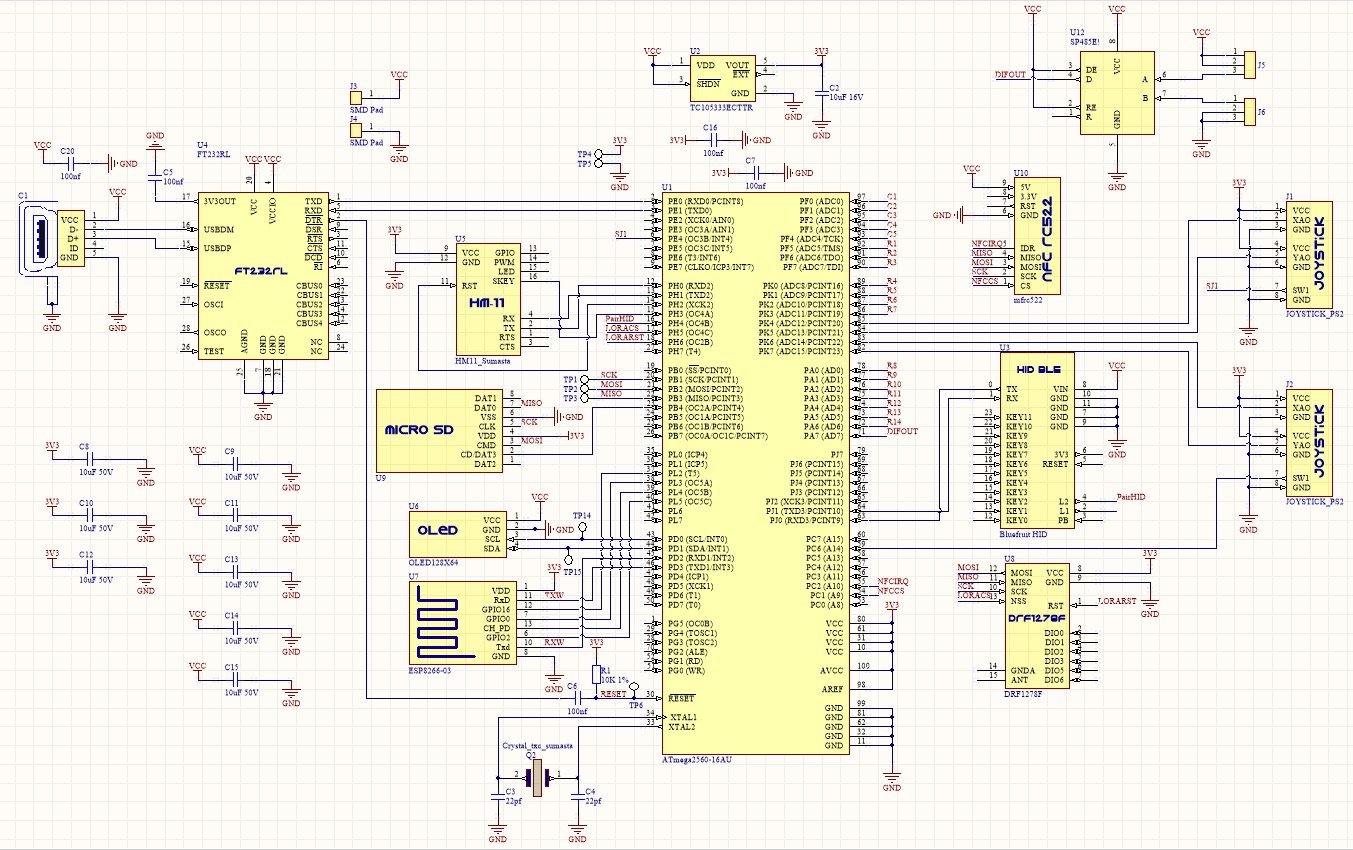
In summary, started on the left side is the standard FTDI IC both for debugging and programming. Taking the most space in the center, that is the main processor itself ATMEGA2560. The Bluefruit EZ key, ESP8266, FT232RL and HM-11 occupy all the Hardware serial port. While DRF1278, MRC522 and the MicroSD card shared the same SPI bus. On top of that, the OLED is the only one connected to the I2C bus. Joysticks on the other hand connect to 4 analog pins available on the microcontroller.
And that was it. It was quite straight forward overall. The time was a lot more spend on making the Altium library for most of the modules and components. Quite frankly that's what I often don't like in using Altium, every single time a unique components/modules is used, there is a great chance that I have to generate the library myself. Well, you know in eagle, most of the time someone else have made the part you need for you.
Discussions
Become a Hackaday.io Member
Create an account to leave a comment. Already have an account? Log In.
Hello, I am a student from China, I also in the design of a keyboard, stm32 master, and add a lot of module, and add a 3.2 -inch touch screen, I'd like to know how you tackle the problem of insufficient usb power supply, thank you
Are you sure? yes | no