 ksk
ksk(continuing from the main description...) The degraded 1 PPS edge is a problem for really precise applications, but I needed only be close to UTC as I use a second 1 PPS source to sync to the correct second and set timing for the rest of my system. That is, I take time from the Linux system and set it on an embedded system that is disciplined by a high-quality 1 PPS.
0%
0%
MR350PS4 GPS serial adapter
Convert the MR350PS4's custom DIN-6 to an RS-232 DB9.
Become a Hackaday.io member
Already have an account? Log in.
Just one more thing
To make the experience fit your profile, pick a username and tell us what interests you.
Pick an awesome username
hackaday.io/
Your profile's URL: hackaday.io/username. Max 25 alphanumeric characters.
Pick a few interests
Projects that share your interests
People that share your interests

 Jac Goudsmit
 Voja Antonic
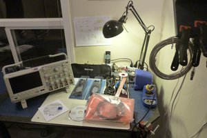
 MagicWolfi
 MS-BOSS