 Damian
How to build the box
Get all the components from the component list.
Solder 11 10k resistors (any value between 1k and 50k should do) in series to create a voltage divider with 12 voltage levels. One end goes to 3.3V, the other to GND. Each voltage level goes to a position of the rotary switch (12 position switch). On the second Box I build, I directly soldered 0805-resistors on to the switch, check the photos for details. The output tab in the center of the switch goes to the analog input (A0) of the NodeMCU.
The I2C oled display connects to 3.3V, GND, D1 (SCL) and D2 (SDA).
The two buttons are normally open type and are connected to D6 (start) and D7 (stop), the other terminal of the buttons goes to GND.
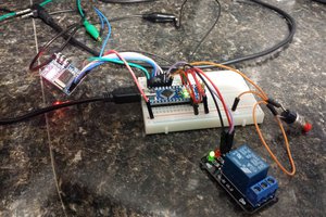
Find a nice wooden box. I used various drill bits and a dremel to make the holes. After installing and testing everything was secured with generous use of hot-melt glue.
The code is available on my Git reposiory: https://github.com/DedeHai/ESP-TogglBox
To upload the code I use the Arduino IDE.
How to use it
At first startup, the software will try to connect to the WiFi. After that fails, it starts the access point with a little configuration page. Connect to the WiFi accesspoint (name on the display) and go to 192.168.4.1
On the config page, enter your WiFi router's SSID and the password. While you are here, also enter the API token that you can get at the bottom of your profile settings at toggl.com. Which reminds me that I probably should mention that you also have to create a toggl account first. And while you are on the toggle web page also create a few test projects. You can track up to 12 projects with a 12-position rotary switch, more if you use a rotary encoder or maybe even a potentiometer.
Now reboot the ESP8266, the data entered in the webinterface gets saved to flash memory.
 Gary
Gary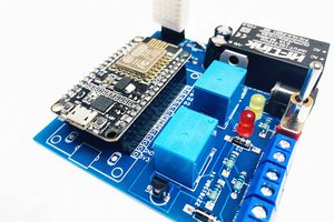
 Abid Jamal
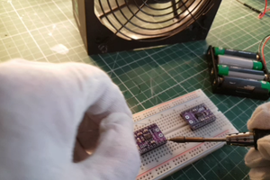
 Debinix
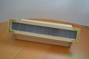
 MobileWill