 Mangus Tiranus
So its been a while since I made an update. As always I've been busy behind the scenes, doing lots of head scratching and getting mild concussion from banging my head against the wall :p
So where am I at?
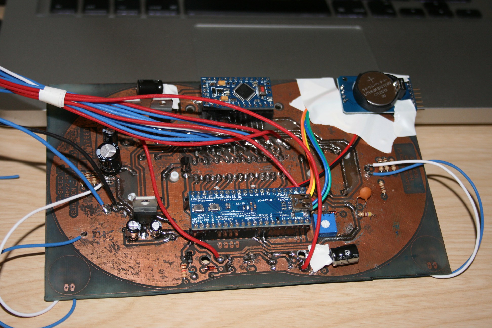
Well I've built the Rev 2 prototype board. YAY, however it really wasn't simple sailing.
Come with me on a journey of frustration and insanity...
I got tired of waiting for the toner transfer paper to come from china. Its still not turned up and I think I might have to log it as an undelivered item in Ebay... So I went ahead and used some magazine paper to do the transfer, and it didnt go quite as nicely as I've seen other peoples transfers go.
While it was better than the baking paper some toner just didnt pass over that well. I think the ink on the magazine paper interfered some what with the heating or mixed into the toner. Not sure.
So I still had to get the sharpie out and fill in some missing or broken bits. But it looked alright and I etched the board. So far so good. A few weak or broken tracks but reenforced them with some solder.
I was going to do a whole solder mask and silk screen layer, but as the solder mask didn't come out as nice as I hoped, i decided not to bother with the silk screen.
I think the issue with the soldermask is I was using a UV torch and it just wasn't strong enough to penetrate into the paint to make it stick to the board correctly. So when I pulled the OHP sheet off it also pulled some of the mask up as well.
Anyway I managed to patch that up and had clean pads for some reflow soldering.
I also got my paste in the post the day after I set the solder mask and was eager to try and solder on the 80 addressable LEDs.
Pasted on and placed the SMD parts, and then I went to a old mini baking oven that was my mums and put it in. I used the reflow chart for the LEDs as a rouge guide knowing the oven wouldn't exactly match it. Hand controlling the temperature dial I preheated and then sent it to the peak temp, and watched through the window to wait for the solder to melt and set.
Well that worked.
I spent the next day drilling all the vias and soldering the rest of the stuff on...
It was time to switch it on. I got my 12v PSU out and wired it in. And turned it on... keeping an eye on the PSU light incase there was a short. (the light normally goes dim if there is)
And nothing.
Nothing turned on, the PSU light was still on so there couldnt have been a short. But then I noticed the jumper wire I was using to power the board was melting and smoking... I quickly pulled the power out of the board before it caught fire.
Turned out there was a short, but because it was on the other side of the 5v regulators my PSU didnt seem to notice.
So the next day i started to look at the board closely. I couldnt find it. I exspected maybe some solder was touching ground where it shouldnt be, or a bad track etch somewhere. I spent hours looking and couldnt find anything.
Using my continuity tester I was able to find that there was certainly a short somewhere from the 5V line, but just couldnt find it anywhere. Then thats when I started to fear the worst. What if some solder paste made contact underneath the many smd LEDs, its certainly possible. If that was the case it would have been a total nightmare to find and fix.
It was at this point a good friend stepped in and suggested a way to isolate where the short was, simply by cutting the power rail traces into segmnts and testing each segment. Starting with the LEDs... Good idea. Easy to repair too.
So I isolated the left array of leds. Nope not there, Thank fluff... Isolated the right array... YAY not there either. So it wasnt underneath the leds. That part of the nightmare was over.
I then managed to Isolate the short to a 1 inch by 2 inch area and I still couldnt find it. Took me a few hours to figure out what 'I did wrong'... My fault entirely.
When the toner didnt transfer quite right I penned on some of the missing tracks and i stupidly got mixed up and penned in a track that wasnt there, I penned a track right from 5v to ground. I mistook a small slither of ground plane for a track from a pin... Stoooopid!
Anyway, I broke the short and fixed the isolation cuts. And powered it up... IT WORKED!
Great.....
I just wish I was ending the post there. Wouldnt that have been nice.
But NOOOoooooo! Something else had to brake.
So last night I was tweaking my code to include the extra leds, in the earlyer mock up I was using 18 LEDs, in this prototype Im using 40 in each array. Setting the number of leds to 40 does something odd... it crashes my main MCU, it shouldnt. I can only assume the faslLED library im using that was ported to stm32 is buggy. Trouble is the crash was also locking out the serial connection, so I was struggling to remove the broken sketch and replace it.
Today, I got one of my spare mini maples and soldered up the legs to it and put in the sketch, placed it onto the board and didnt realise it was sitting one pin to the left. Powered on and killed it :( Dead chip. not really sure how as it was only taking 5v in a input pin, but its now dead... Doesn't power up, and if I try the chip just heats up dramatically.
So i got out my last spare. Placed it in correctly. AAAAND... That died too :( no idea why again. Same heating up. May be they came from the same batch of dodgy builds. Or maybe I just broke them :(
But no fun, I've now ordered some more from china, but its going to take weeks for them to turn up.
I can use this time to investigate what went wrong.
Anyway heres some pics :)
Sorry for this long long LOOONG post :D
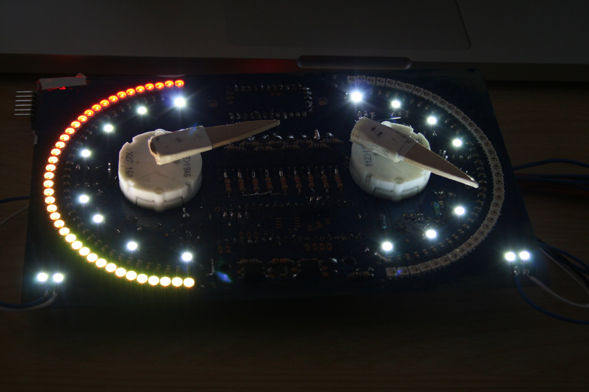
Oh before I forget to mention, i think the transistor that controls the white backlight LEDs popped. They seem to be stuck on. no code is running them to be on.
Discussions
Become a Hackaday.io Member
Create an account to leave a comment. Already have an account? Log In.