Close
0%
0%

Servo Breakout for WeMos D1 Mini

Connect servos to your ESP8266 dev board.

Similar projects worth following
Starting from
$8.00
CRImier has 512 orders / 41reviews
Ships from Latvia, Netherlands
Servo shields for the WeMos D1 Mini boards.

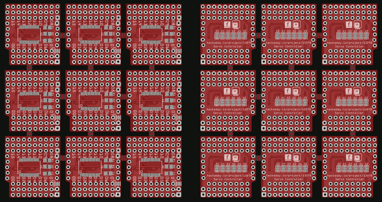
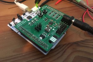
I thought I will try to make some shields for the WeMos D1 Mini, because it's one of my favorite ESP8266 boards. There is already an official motor controller shield (though I can't get it to work reliably), so I decided I will make some servo shields.

d1servo16ch.zip

Non-panelized gerbers for 16ch board.

Zip Archive - 52.04 kB - 05/22/2019 at 15:02

Download

pca9685c.fzz

Fritzing for 16ch boards

x-fritzing-fzz - 65.39 kB - 05/22/2019 at 14:59

Download

gerber.zip

Gerbers for 9 16ch boards.

Zip Archive - 442.44 kB - 05/22/2019 at 14:46

Download

wemos-servo8.zip

Gerbers for the 8-channel board.

Zip Archive - 170.95 kB - 08/23/2016 at 13:00

Download

wemos-servo8.fzz

Fritzing design of the 8-channel board.

x-fritzing-fzz - 31.74 kB - 08/23/2016 at 13:00

Download

  • Maybe SX1509?

    deʃhipu12/19/2020 at 21:34 0 comments

    It's been a long while since I made this shield, and the PCA9685 chip that it uses has been in service for driving servos even longer. Meanwhile, I have been on a lookout for a more modern and smaller chip that could provide a similar function. The PCA9685 is not perfect, because it is actually a LED driver, which just happens to have adjustable PWM frequency allowing us to abuse it to generate a 50Hz servo signal. Still, it contains constant-current drivers that we don't need, and we only use a small part of its duty cycle range.

    So what could be other chips that we could possibly use? If you look around a little for "PWM chips", it seems that chip manufacturers only recognize two use cases for PWM signal: buck/boost converters and LED drivers, and in both cases they prefer relatively high frequencies, at least 29kHz, if not 33Mhz. That is useless for us, sadly, so we need to look in other places.

    Recently I have stumbled upon a really weird chip, SX1509. It's I²C-controlled GPIO multiplexer, but with some extra features, that include voltage level shifters, a keyboard matrix scanner and, last but not least, a PWM LED driver. So maybe we could use it for our servos?

    I ordered a breakout board with this chip somewhere at the beginning of this year, and I have been putting away working on it for a looong time. But now with the holiday break, I decided to finally sit down and try it. So I downloaded the datasheet, got a Trinket M0 running CircuitPython out of one drawer, and a pocket oscilloscope out of another, and I started to poke at the registers.

    Sadly, this is another failure, for two reasons: first, the slowest frequency I managed to get for the PWM signal is 121Hz, over twice as much as the required 50Hz; second, it only has 8 bits of resolution for the duty cycle length, and that's over the whole range, of which we only need a small part, so it would be even worse than the 12 bits we get with the PCA9685.

    But I guess I will keep it in my drawer if I ever need to multiplex GPIO pins while level-shifting to two different voltages, scanning a keyboard matrix and blinking LEDs.

  • New Seller

    deʃhipu08/20/2020 at 20:20 0 comments

    Since there was a large demand for those shields, they can now be bought again at Tindie from @Arsenijs: https://www.tindie.com/products/crimier/16-channel-servo-shield-for-d1-mini-v2-by-deshipu/

  • New Batch

    deʃhipu02/21/2019 at 12:37 0 comments

    I have sold the last of those servo controllers on Tindie a while ago, coming up to the total of 128 units sold, but people keep adding it to their wish list, so I decided to go and make another batch. This time I'm not going to go to a fabricator — I discovered that I actually enjoy the process of assembling them myself, and with just a few orders a month I have more than enough time for that. So I just ordered the PCBs. However, the times have changed — back then you could only order cheap PCBs up to 5x5 cm in size, while today 10x10 cm is the standard. So I panelized the latest version of the design, to optimize the yield:

    It's a bit of a pain to do in Fritzing, and I made several mistakes on the way (sorry for the people at the PCB fab who already started reviewing it when I cancelled the order), but after the third try everything seems to be correct.

  • Fabrication and Version 2.0

    deʃhipu12/04/2017 at 10:17 6 comments

    There is a relatively high demand for this board on Tindie, so when I sold the last of the 75 hand-assembled modules, I stated looking at fabrication options. Unfortunately, for a board with so many soldering points (the servo socket headers), it was relatively expensive. I didn't realize that the work I was doing by hand is worth so much. In any case, I asked several fabrication services for quotes, and since I didn't want to increase the price too much, went with the cheapest one, which turned out to be PCBWay.

    They were very helpful all along the way. The bill of materials CSV file I sent them didn't parse quite well for them (probably because I wrote it by hand in Vim), but they had no problem with me just including an ASCII-art table in the e-mail instead. On every step of the process they sent me photos, asking if it looks correct. They also tried to catch possible errors themselves: for example, my BOM didn't include the stacking headers that I add to every module — they saw them in the photo and asked if they need to be added. (I send them unsoldered, so I add them later myself). There was also one small glitch when they initially wanted to use straight pin headers instead of angled ones, but because they sent me the photo I could point out the mistake, and there was no problem switching to the correct headers.

    I choose the cheapest shipping (again to keep the price low), but it still arrived without problems in 2 weeks. Here's a photo of the package I got:

    The anti-static bags on the bottom contain the soldered panels (I choose to depanelize them myself, again to save costs). The rest of the bags are all the left-over parts, including one unsoldered PCB panel of 5 modules.

    A quick test shows that the modules work very well.

    All in all, I'm very happy with them. You can buy the new modules on Tindie here: https://www.tindie.com/products/deshipu/16-channel-servo-shield-for-d1-mini-version-20

  • Faster Assembly

    deʃhipu08/01/2017 at 20:14 0 comments

    I recently got myself a cheap hot air gun, and as a test for it, I assembled one panel of the servo controller boards.

    I must say that it really changes everything. While applying the solder paste is still a little slow without a template, soldering all the parts is a moment, and they magically snap into their correct positions. I had a few solder bridges due to too much solder paste in some places, but a solder suction tool took care of those easily.

    You can see on the photo the testing probes that I'm using to test all the shields. The result this time was 100% working.

    Soldering the pin headers was even faster, at least compared to the manual process I used before. How come I didn't get one of those hot air things earlier?

  • Assembling and Testing

    deʃhipu04/04/2017 at 11:34 0 comments

    The package with the chips finally arrived, so I can assemble the remaining boards. Soldering the TSSOP packages by hand is not terribly difficult, but it can still be tricky. So I'm not trusting myself, and apart from visual inspection I decided to also do at least basic testing of the shields. On the other hand, I have to ship them with the headers unsoldered, so I can't simply plug them in and see if they work. Fortunately, I have some of those testing probes lying around:

    With that, I can easily check that the devices show up in an i2c scan, and that they can wiggle the servo. It''s not a full test -- that would have taken way too much time -- but it does cover the most common failure modes. Since I'm only making a few dozens of them, and I can assemble them as they are being ordered, I don't think I need to make a more sophisticated testing rig just yet.

  • Version 1.0 of the 16-channel Shield on Sale

    deʃhipu03/24/2017 at 17:48 0 comments

    After the prototypes that I put on sale on Tindie sold within 2 days, I decided to try and make a larger number of the servo controller shields. I choose to do it with the 16-channel PCA9685 shields, because to be honest I don't trust my own C code enough to inflict it on unsuspecting people. In any case, you can now buy the production version of this on Tindie here:

    https://www.tindie.com/products/deshipu/16-channel-servo-shield-for-d1-mini-version-10/

    I ordered about 90 PCBs (the Elecrow's 10x10cm offer is the best bang for the buck), but so far I only had components to assemble 5 of them. More components ordered, and I will put them in stock as they arrive. Here's a photo of the ready PCBs:

    I also wrote proper documentation manual for this board, it's available here: http://16-channel-servo-shield-for-d1-mini.readthedocs.io/

  • Usage Examples

    deʃhipu03/01/2017 at 15:43 0 comments

    So here is example code you can use to communicate with the 18-channel and 20-channel servo controllers, for different environments that you can run on the ESP8266:

    MicroPython

    import ustruct
    from machine import I2C, Pin
    i2c = I2C(scl=Pin(5), sda=Pin(4))
    address = 0x10
    servo = 4
    position = 1500
    i2c.writeto_mem(address, servo, ustruct.pack("<H", position))
    

    NodeMCU

    address = 0x10
    servo = 4
    position = 1500
    sda = 2
    scl = 1
    i2c.setup(0, sda, scl, i2c.SLOW)
    i2c.start(0)
    i2c.address(0, address, i2c.TRANSMITTER)
    i2c.write(0, servo)
    i2c.write(0, bit.band(position, 0xff))
    i2c.write(0, bit.rshift(position, 8))
    i2c.stop()
    

    Arduino

    #include <Wire.h>
    void setup() {
        int address = 0x10;
        int servo = 4;
        int position = 1500;
        Wire.begin();
        Wire.beginTransmission(address);
        Wire.write(servo);
        Wire.write(position & 0xff);
        Wire.write(position >> 8);
        Wire.endTransmission();
    }
    void loop() {
    }
    

  • Selling Prototypes on Tindie

    deʃhipu02/25/2017 at 02:00 0 comments

    I decided to give Tindie a try and sell the prototypes of servo shields that I've built. I have three of each of the 16-channel and 20-channel ones. You can get them here: https://www.tindie.com/stores/deshipu/

    I'm basically just getting rid of them, since the project is complete and I don't really need so many servo controllers -- there are only so many robots I can build at once. On the other hand, it would be a waste to just throw them away or let them rot in my drawer -- so I'm selling them.

    While they are all manually tested, keep in mind that they are still prototypes -- purple PCBs, hand soldering, possible hidden bugs -- I will support them the best that I can, but I can't replace them (because I only have 3 of each and I'm selling them all) if they stop working. I can fix bugs in the firmware for the 20-channel shield, but then you will need an ISP programmer (or any Arduino, in fact) to re-program them -- I can help with that, but it does take some time and effort to setup. The 16-channel servo uses an off-the-shelf chip, so there are not likely to be any bugs.

    This is also an experiment in gauging the interest in this. If they get added to a lot of wishlists, I might consider making a larger batch of them.

  • PCA9685

    deʃhipu02/23/2017 at 15:56 3 comments

    @Jonathan Beri asked in the comments why I didn't use PCA9685, but instead went with an ATmega and my own code. To be honest, this is mostly because this project is the continuation of my #Servo Controller project, in which I used a Pro Mini board.

    But that got me thinking, and I went and checked if I can get some of those chips cheaply, and I went ahead and designed a PCB for them:

    I was actually so happy with it, that I went ahead and ordered them from OSHPark. Today the boards arrived, and I assembled one and tested it:

    It works perfectly fine. You only get 16 channels (that's why I could fit it on the standard D1 Mini shield), but you can stack 64 of those boards (the address selection jumpers are on the bottom). Pretty neat.

View all 23 project logs

  • 2
    Step 2

    Populate the PCB -- solder the ATmega328p, the reset resistor (10kΩ), the I2C pullup resistors (10kΩ, optional), capacitor (10-1000µF, optional). Solder the pin headers for the servos and power, and an extra pin or wire for the reset.

  • 3
    Step 3

    Connect your ISP programmer to the 3v3, GND, MISO, MOSI, SCK and Reset pins as follows:

    If you are making the 2ch version, the pin names are printed on the PCB. Get the source code from https://bitbucket.org/thesheep/d1mini-18ch-servo/src for the 18-channel version or https://bitbucket.org/thesheep/d1-mini-20ch-servo/src for the 20-channel version. To flash the 18-channel version, use Arduino IDE. To flash the 20-channel version, run "make flash" in the firmware directory.

View all 5 instructions

Enjoy this project?

Share

Discussions

Thomas wrote 01/21/2017 at 07:58 point

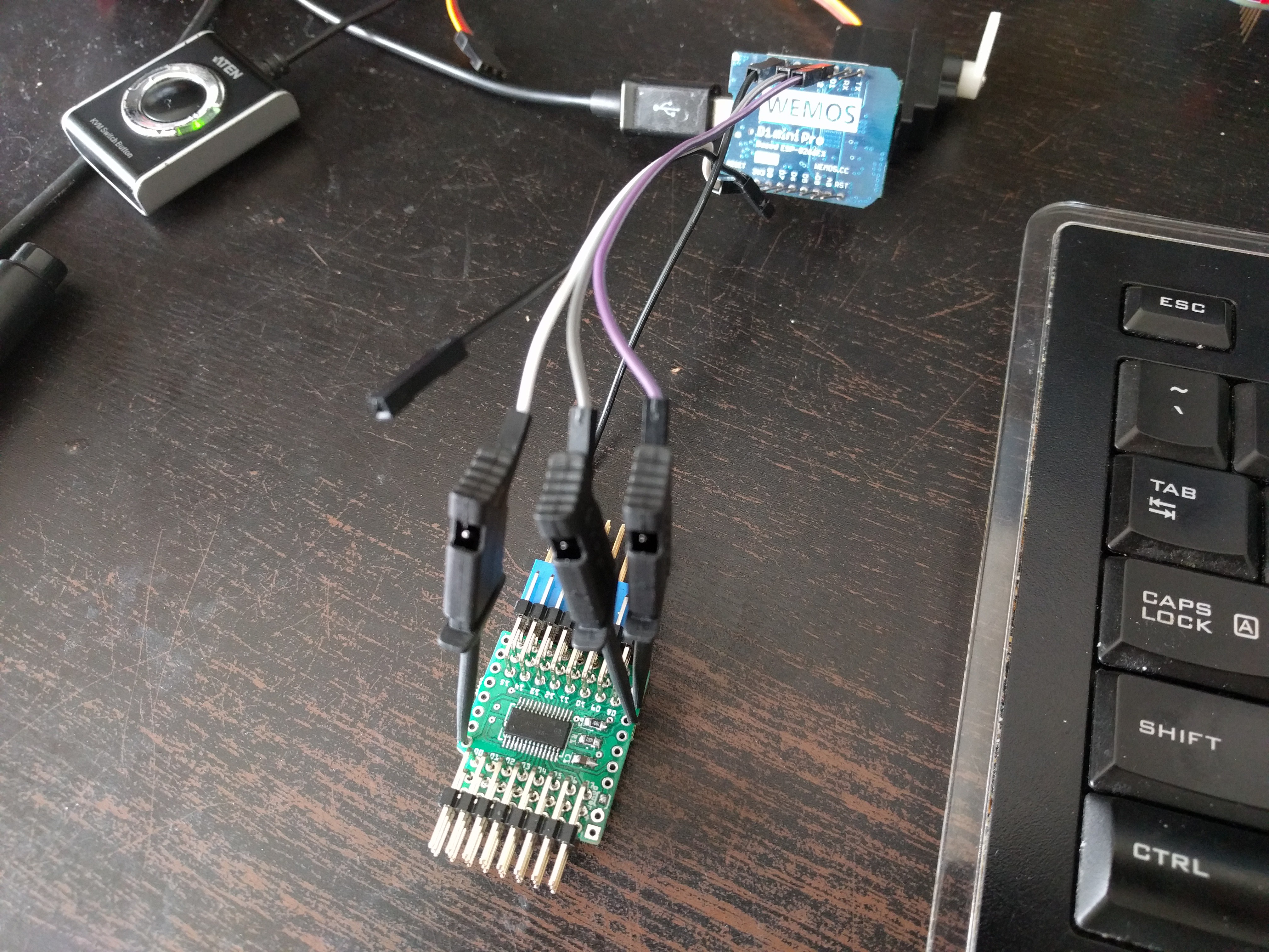
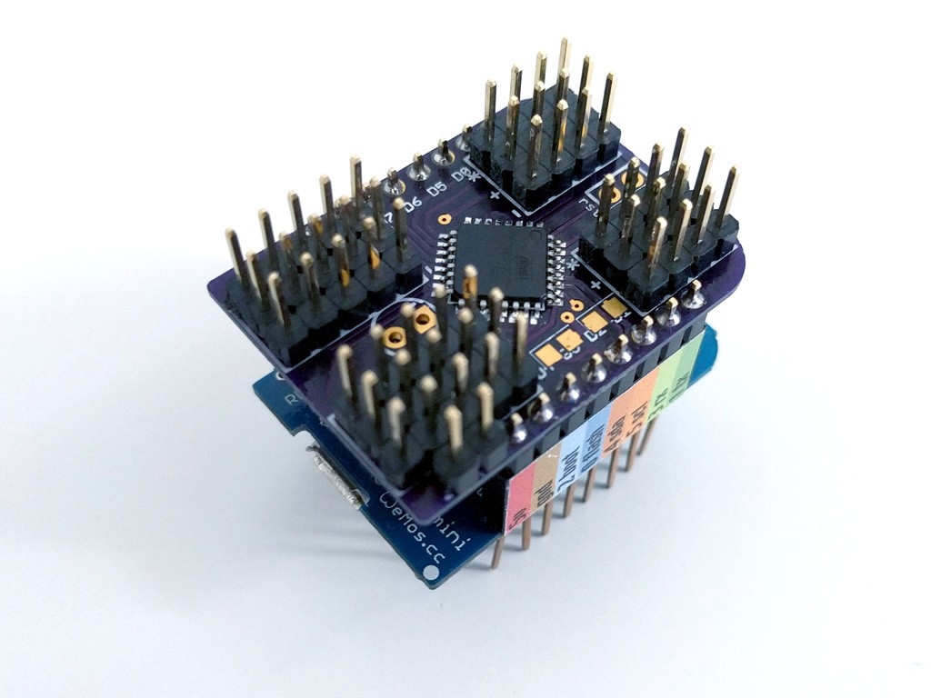
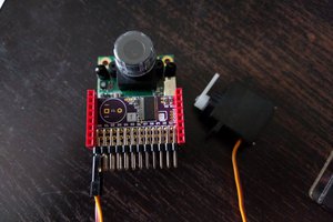
Maybe I've worked too long in the field of electrical reliability to put too much trust in the mechanical fitness of a two rows of 8 pin headers to support the mass of an assembly of a rather dense assembly [shield-PCB+48 pin headers+16 3pin connectors+attached cables]. It might be advisable to provide mounting options that take away mechanical strain and stress from the pin headers. Also such an assembly easily draws a lot of current, even if no servo is ever stalled (0.2A x 16). The requirements of an adequate power supply (with sufficiently designed ground) might also be a good thing to be getting aware of.

  Are you sure? yes | no

deʃhipu wrote 01/21/2017 at 09:24 point

There is a connector for a separate power supply for the servos, and 99% of the bottom layer is a ground fill. As for mechanical ruggedness, you can always put the shields on the bottom, and the D1 Mini (which is relatively light) on top. But the shield is quite small and feels pretty solid. I agree it would be nice to have mounting holes, unfortunately there isn't much room left for that.

  Are you sure? yes | no

Thomas wrote 01/21/2017 at 15:13 point

You've got a point. I'm just not a big fan of "shields"  for different reasons.

By the way, an ESP-14 can control up to 15 servos without external controller. This should work even if the integrated STM8S003F3 has a 3.3V power supply.

Edit1 in response to @Radomir Dopieralsk: http://www.watterott.com/index.php?page=product&info=4831&dl_media=6623&x0993b=33c134530245f3b2921d85e84fa5d152

Edit2 in response to @Radomir Dopieralsk: if you need the ESP8266 serial interface for controlling the MicroPython console you'd be down to controlling just 13 servos (maybe 14 with some tricks).

  Are you sure? yes | no

deʃhipu wrote 01/21/2017 at 15:25 point

ESP-14? Is that another module with the ESP8266 on it? How does it do without an external controller, if you can only use 11 gpio pins on the ESP8266, and that's if you re-use the serial pins... Do you have a link?

  Are you sure? yes | no

deʃhipu wrote 01/21/2017 at 15:50 point

Ah, I see, so you program the stm8 chip inside. That's nice, but I want to use the esp8266 to run micropython on it, stm8 doesn't work for me.

  Are you sure? yes | no

deʃhipu wrote 01/21/2017 at 16:21 point

Just reply to the message one level above...

Looking at the pinout of the esp14 module, I don't see any esp8266 pins broken out -- so I don't think you can program the esp8266 on it, only the stm8.

  Are you sure? yes | no

Thomas wrote 01/21/2017 at 18:26 point

The ESP8266 can be programmed the usual way through pins 10 and 11 when pin 14 is low. The intent of the hardware design is to use the ESP8266 UART for communication with the STM8S, but it's also possible to use a simple serial protocol to transfer the data for servo control from E_GPIO0 to any STM8S GPIO.

Another option would be to make the STM8S listen to ESP8266 TX and filter out servo set commands from the data stream. There are a few more options. and depending on on-line console communication requirements, trade-offs and time spent on optimizations, anywhere from 13 to 17 servos can be controlled without using port expanders (like shift registers).

Please refer to the discussion here for another take on using the ESP-14: https://hackaday.io/project/16097-eforth-for-cheap-stm8s-value-line-gadgets#j-discussions-title

Thanks for the message level hint :-)

  Are you sure? yes | no

Jonathan Beri wrote 01/20/2017 at 16:48 point

Are you thinking about a PCA9685-based shield as well?

  Are you sure? yes | no

deʃhipu wrote 01/20/2017 at 17:16 point

No, I used those with Feather HUZZAH, and I'm not impressed. They only have 16 channels, the I2C registers are a bit complex (enough to need a library for it) and they are actually for driving LEDs, not servos. With a simple atmega I have everything they would give me, plus 4 more channels, and it's cheaper.

  Are you sure? yes | no

Jonathan Beri wrote 01/20/2017 at 18:47 point

I've used it pretty happily in other servo projects but those are fair points. Are you able to achieve better resolution and/or faster frequency with the atmega? 

  Are you sure? yes | no

deʃhipu wrote 01/20/2017 at 18:53 point

The frequency I'm using is fixed at 50Hz, because that's what the servos want. I can do 1µs resolution at that frequency, which with my servos translates to 0.01° angle (except for a corner case that I just found where two servos are in really similar positions -- then it's more like 5µs).

Don't get me wrong, the PCA9685 is a great piece of silicon and I would use it -- if I didn't write the code to do it without it first. For Tote there is an extra advantage -- I only need one chip for both the robot behavior and the PWM -- though I will be moving away from that anyways.

  Are you sure? yes | no

Eric Hertz wrote 01/23/2017 at 01:22 point

so, bitbanged PWM on 20 channels with 1us resolution? and presumably serial of some sort? Impressive!

  Are you sure? yes | no

deʃhipu wrote 01/23/2017 at 11:16 point

Well... I found recently a bug where if two channels are too close to each other, one of them wouldn't work -- so I had to modify it, so that you only have 1µs resolution when all the channels are at least 10µs apart from each other. When two or more get too close, they get merged into the same signal. So in the worst case, where all the channels are within 10µs of the first one, you only get 10µs resolution.

The i2c communication happens without interrupts, so fortunately it doesn't affect the timers.

  Are you sure? yes | no

deʃhipu wrote 01/20/2017 at 18:54 point

By the way, making a PCA9685-based shield should be extremely straightforward -- it would basically be just all the connections.

  Are you sure? yes | no

deʃhipu wrote 01/20/2017 at 20:50 point

Hmm, it's even more straightforward than I thought:


  Are you sure? yes | no

Mike Causer wrote 10/19/2016 at 01:17 point

Time to put my stash of SG90s to good use.

  Are you sure? yes | no

Craig Hissett wrote 09/14/2016 at 17:00 point

I need at least two of these in my life!

Awesome work matey!

  Are you sure? yes | no

Similar Projects

Does this project spark your interest?

Become a member to follow this project and never miss any updates