

The motivation for this project: Lucid Dreaming
Have you ever had a dream where you realized, "Hey, I am dreaming"? These unusual dreams are called Lucid Dreams: you are aware that you are dreaming. You might recognize this concept from the blockbuster film Inception, which revolves around the idea of lucid dreaming.
With that in mind, what kind of problems and challenges can Lucid Dreams solve?
- Around 24.4 million Americans are suffering from PTSD-related disorders at any given time. (PTSD Statistics) Lucid dreaming have been considered as a promising treatment for Nightmare disorders and Post-traumatic stress disorders. Hence, it could be a valuable tool in managing with mental health issues. (Gavie, J, & Revonsuo, A.)
- Research into lucid dreams can yield more information about the inner workings of our brain. For instance, Voss et. al. used lucid dreaming to study the mechanisms behind higher-order consciousness. (Voss U. et al.)
- We all can benefit from Lucid dreaming: we can defeat our phobias, have creative dreams, practice real-life skills, and do much more to improve our waking lives.
Therefore, it is clear that lucid dreams not only allow mental well-being, but also brings about promising clinical treatments as well as potential scientific research. Thus, the ultimate goal of the OpenLD project is to make thee opportunities available to everyone, especially to the immense Hacker community.
For more information, you can read through an excellent article about lucid dreaming by HowStuffWorks here.
What is the goal of this project?
While some may be able to experience these unique dreams at will, most of us need extensive effort to become proficient lucid dreamers. Therefore, OpenLD aims to facilitate the process of lucid dreaming for everyone. Also, the project will also attempt to create a eye-signal "communication link" between the lucid dream and the real world, which would be a valuable research tool. For a proof-of-concept, this project will establish a two-way dream-world communication and solve a simple arithmetic problem from within a lucid dream.
There is also a second goal for this project: to increase interest in the subject of sleep research and Brain Computer Interfaces (BCI). I hope this is an intriguing example of how anyone can develop an automated BCI system that allows neuroscience research and that the OpenLD project will inspire you guys to try develop your own custom Brain-Hacking projects!
How does this work?
When we sleep, we go through a series of different sleep stages, with one of them being REM (Rapid Eye Movement) sleep. This is when dreaming takes place. (Voss U. et al.)
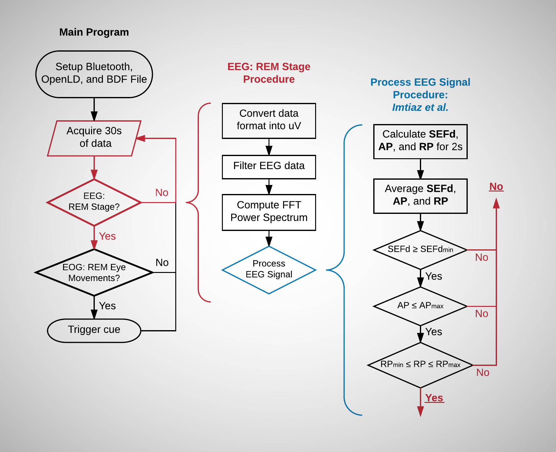
OpenLD will analyze the EEG brainwaves and EOG eye signals to detect when the subject is dreaming. It will then trigger a stimulus (alarm, lights, etc.) in order to wake up the dreamer or create a cue to help the dreamer become aware that he/she is dreaming. In Lucid dreaming jargon, this tool will help the dreamer to induce lucid dreams through WILD (Wake-Initiated Lucid Dream) or DILD (Dream-Initiated Lucid Dream). These terms are described by Stephen Laberge and Donald J. DeGracia in the article here. (DeGracia et al.)
One important peculiarity to note is that our physical eye movements correspond to our dream during REM sleep. For instance, if one looks to the right in the dream, his/her physical eyes would do the same. (Laberge, Stephen) Therefore, we can use this to create a communication link between the two worlds through a Morse code-like system. In our case, the OpenLD platform will detect electrical eye movement signals (EOG, Electro-oculography) for in-dream communication.
What is the plan?
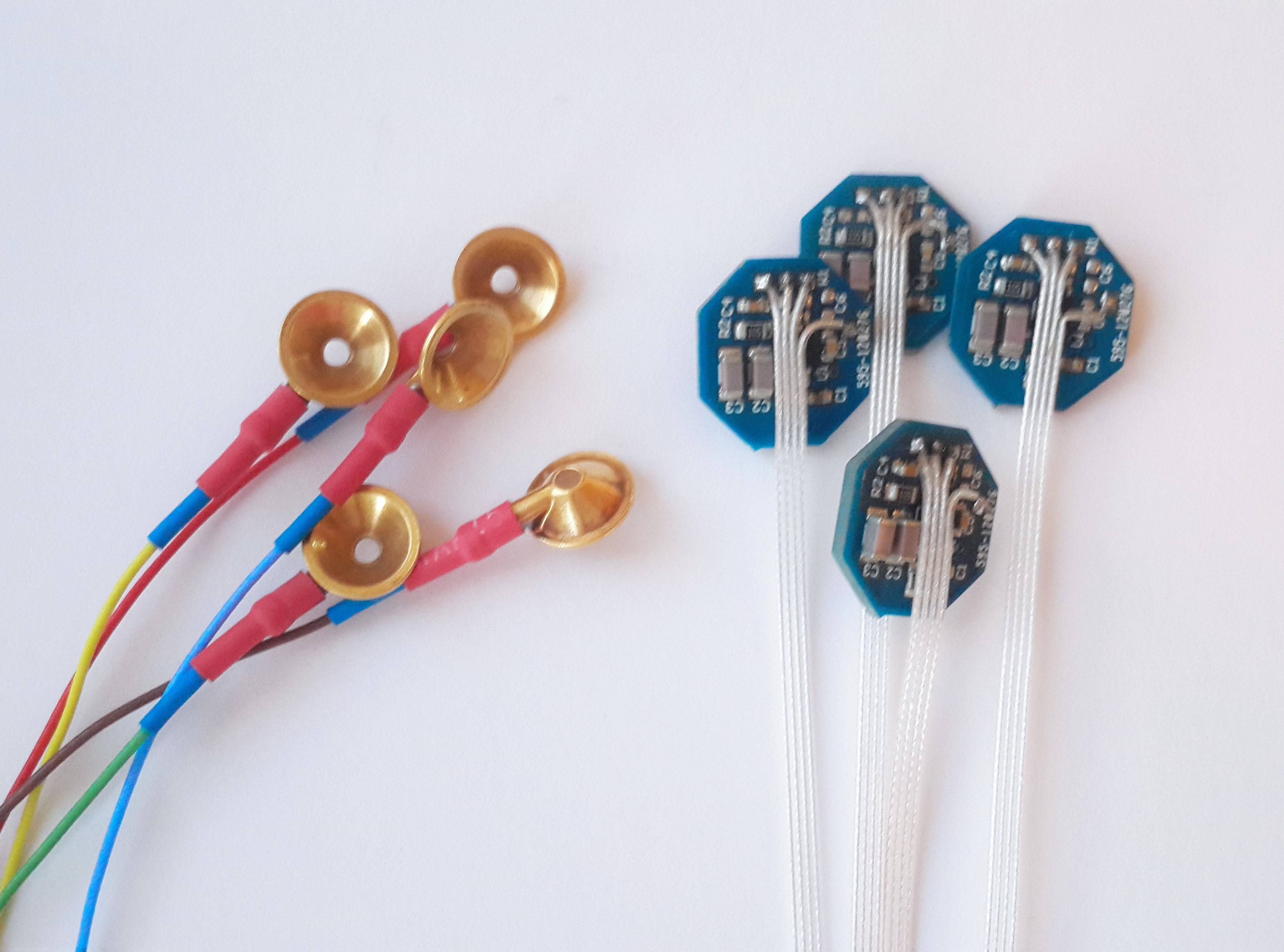
The primary hardware for this project is going to be an Electroencephalogram (EEG) device. This will be used to record and analyze brainwaves during sleep in order to induce and study lucid dreams.
The software is the most important and challenging part of this project. A program that analyzes the brainwaves...
Read more »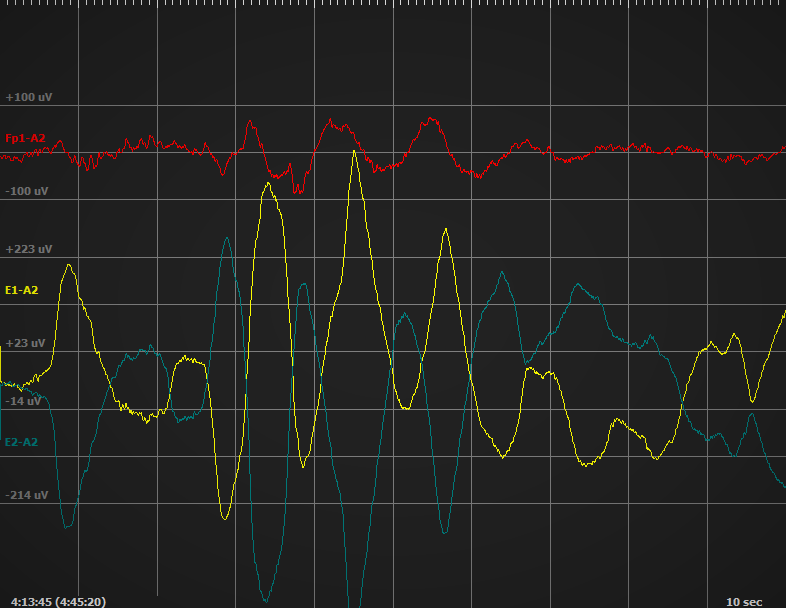
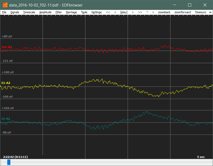
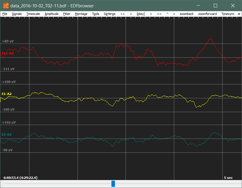
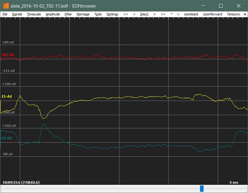

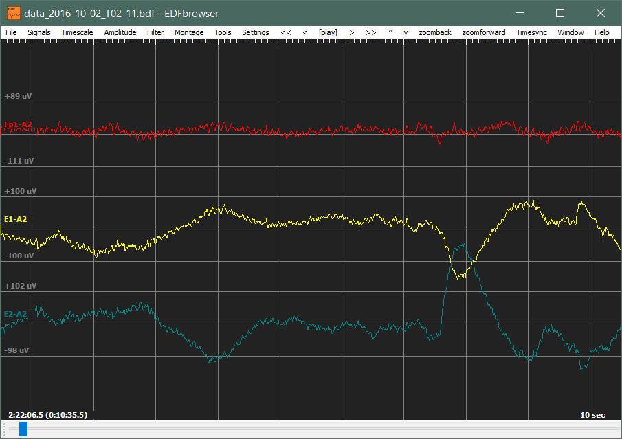
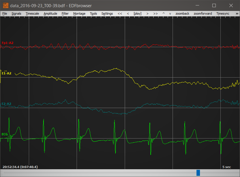
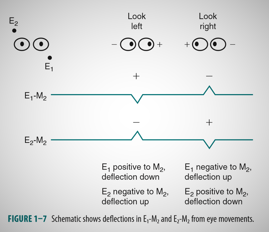
 As you can see from the above figure, eye movements produce deflections which are always out of phase between the two EOG channels.
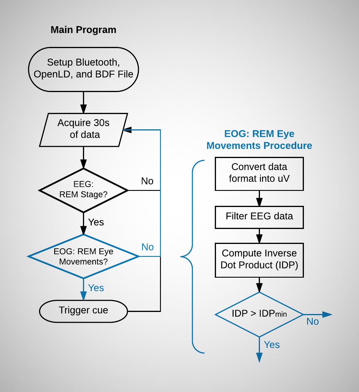


 Gabriel do Vale Rios
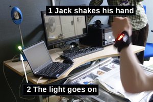
 matt oppenheim
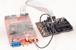
 Colin O'Flynn
 andrew.powell
Hi, i just found your project and wow! It merges different disciplines i would like to skill. Do you guys are still working on it? I'm highly interested in contribute.