EEG Hardware Description

Electroencephalogram (EEG) is a procedure that measures the electrical activity within the brain.
In this project, a custom built EEG device (CAD screenshot above) will record and analyze brainwaves, which will be used to induce/research lucid dreams.
Component Selection for the EEG Hardware
This board contains an ADS1299 chip from Texas Instruments, which is an analog front-end IC containing 8 EEG amplifiers and delta-sigma ADC's. Thanks to this IC, this tool can record 8 channels of high resolution 24 bit EEG signals at a sampling rate of 250 samples per second. This chip is accompanied by a powerful ARM Cortex-M4F microcontroller (STM32F407VG) which handles the data from the ADS1299.
To transmit the data to the PC, an RN42 transceiver module is used to send the EEG signals via a Bluetooth connection. This allows the device to be used wirelessly, which makes it portable and easy to handle. This will be especially important as the mess of electrode leads will be a pain to manage during an EEG session.
Note: The device USB port should NEVER be connected to a main power supply. This can potentially be lethal and, under no circumstances, should it be ever attempted.
Project Files for the EEG Hardware PCB

Schematics of the OpenLD - ADS1299 Data Acquisition stage
The Schematic and the PCB design files (gerber files included) are located in the Files section of this project page. Unfortunately, as of right now, the project files are in an Altum Designer format. However, this format will be changed to other more open source friendly CAD software (Circuit Maker, KiCAD) for later revisions of this board.
Now time for the build
EEG Hardware Build Process
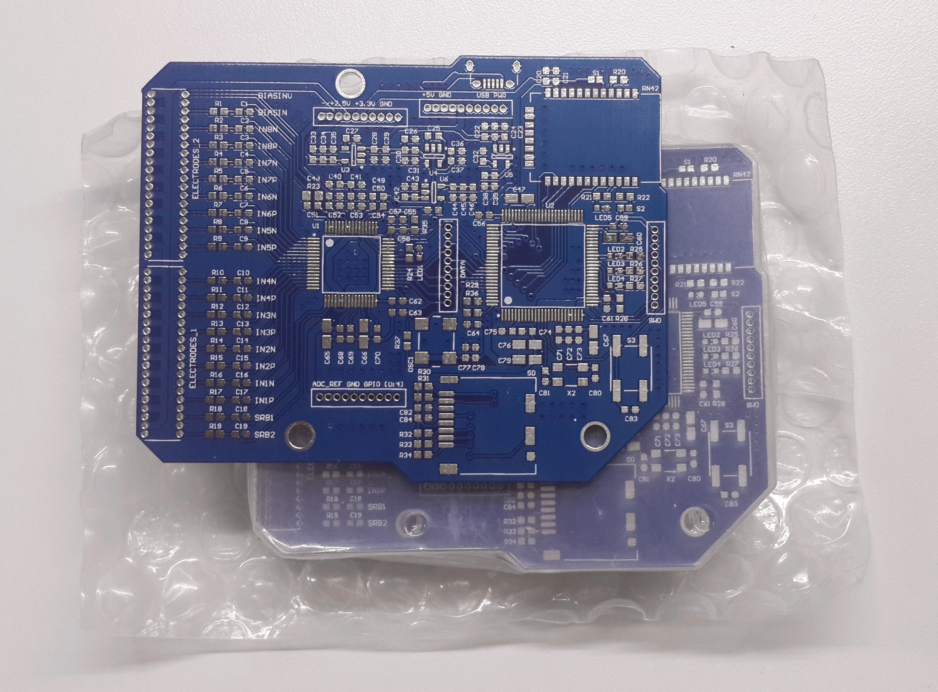
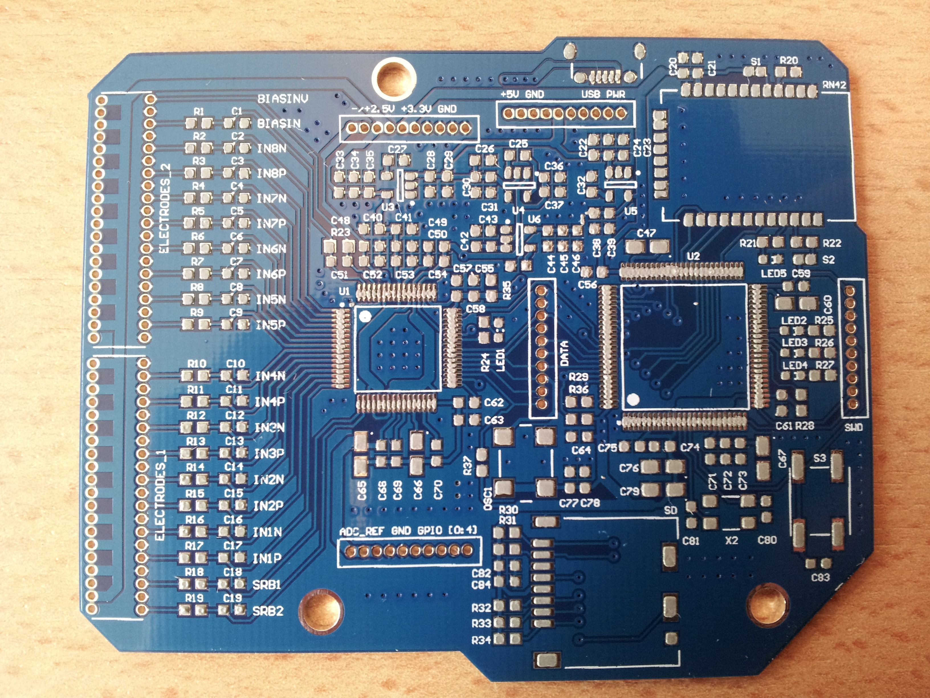
The manufactured PCB's
Applying Solder Paste

 Random note: The solder stencil used above is made out of disposable aluminum pan. It is much easier to make (but more fragile) than the well known method of using soda can aluminum.
Components placed, and now ready to be cooked in the oven:
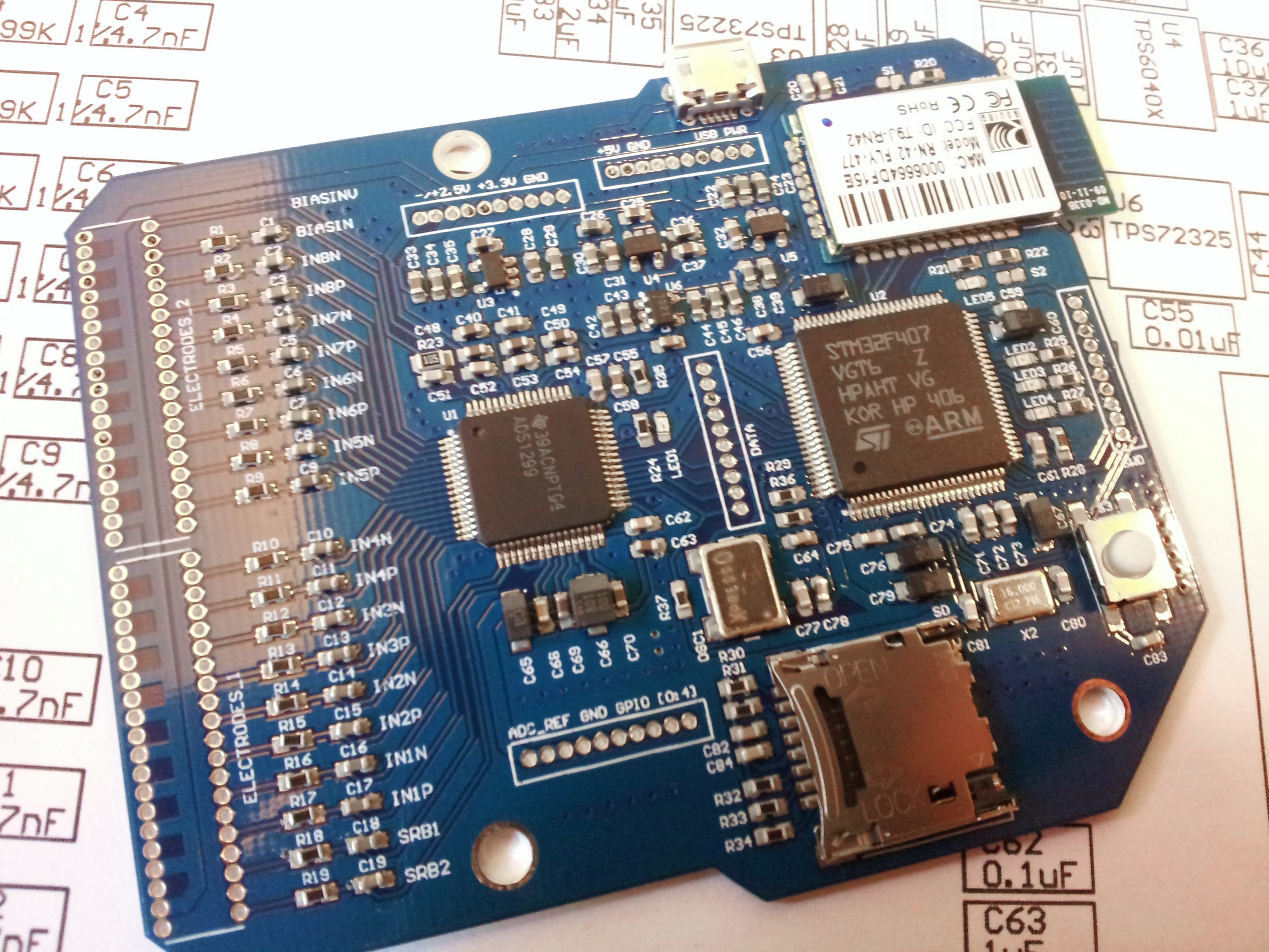
There it is. The board is done.
In the next update, I will be adding an enclosure and soldering appropriate connectors for the EEG board. This will more or less cover the main hardware side of this project.
Discussions
Become a Hackaday.io Member
Create an account to leave a comment. Already have an account? Log In.