0%
0%
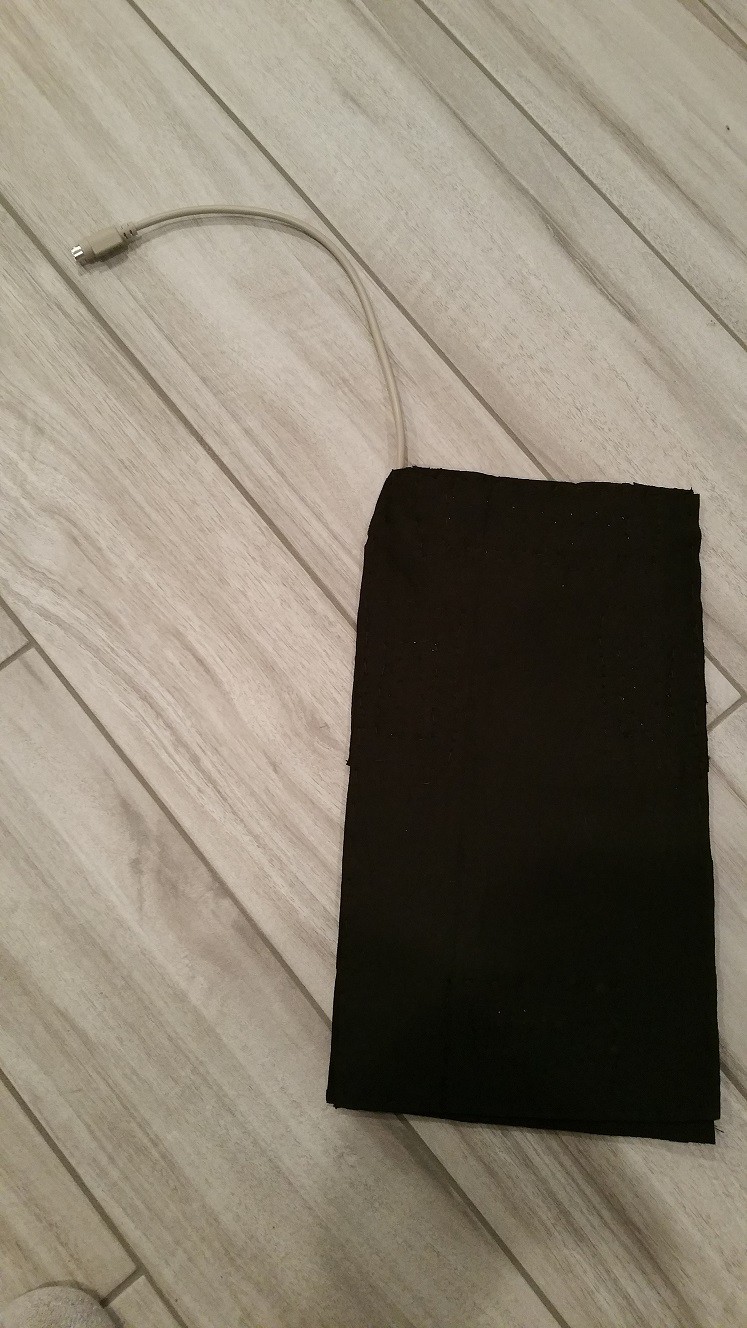
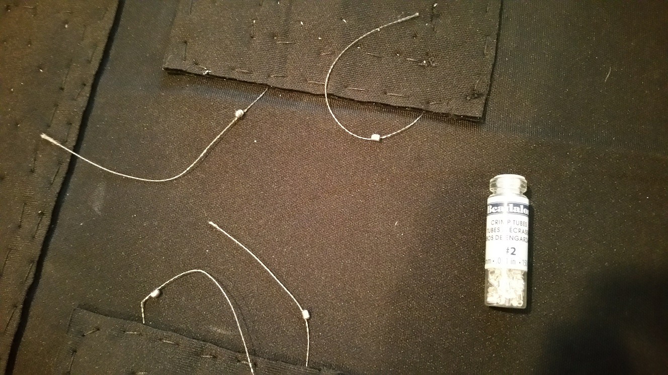
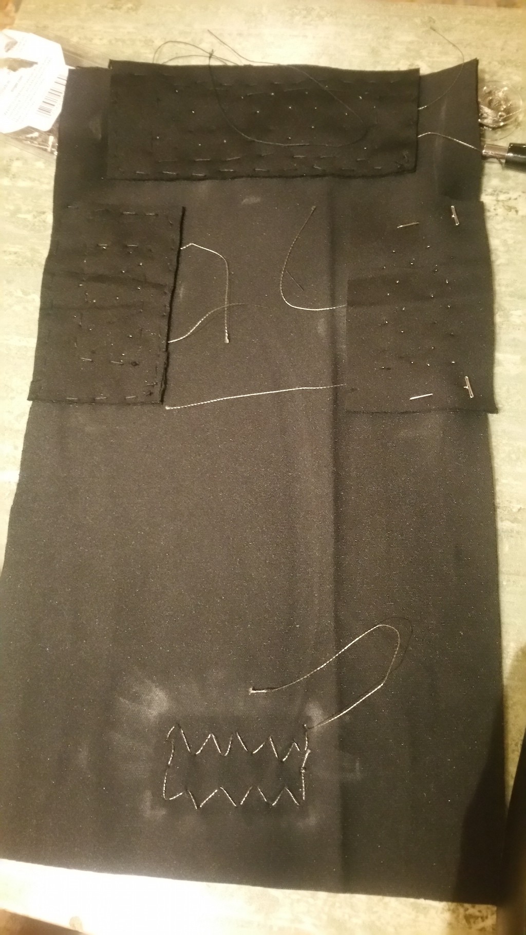
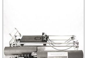
$50 Foot Controlled Mouse
Reimagining expensive commercial accessibility solutions with new prototyping materials
Become a Hackaday.io member
Already have an account? Log in.
Just one more thing
To make the experience fit your profile, pick a username and tell us what interests you.
Pick an awesome username
hackaday.io/
Your profile's URL: hackaday.io/username. Max 25 alphanumeric characters.
Pick a few interests
Projects that share your interests
People that share your interests
 joseph
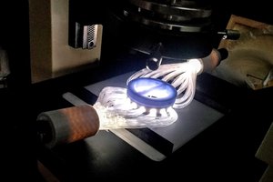
 Zachary Marlow
 Peter Sinclair
 Dan Maloney