 [skaarj]
First - project logs shortcuts:
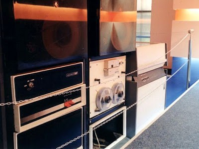
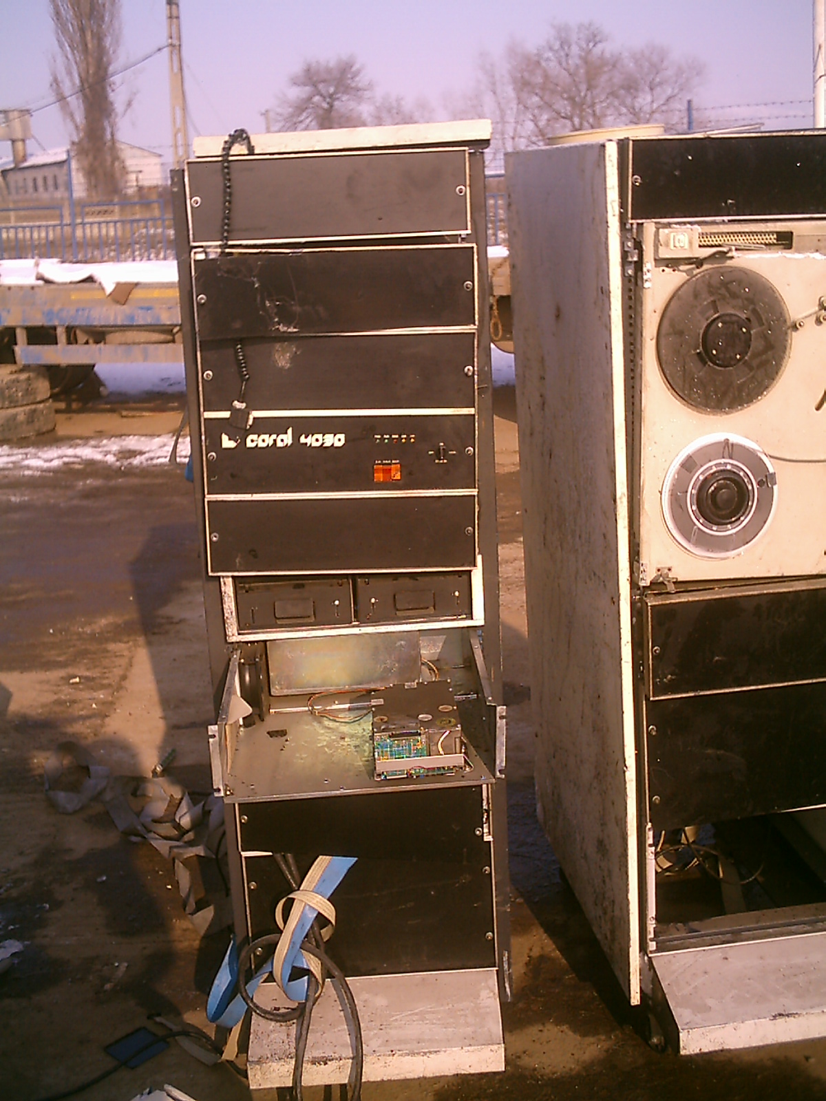
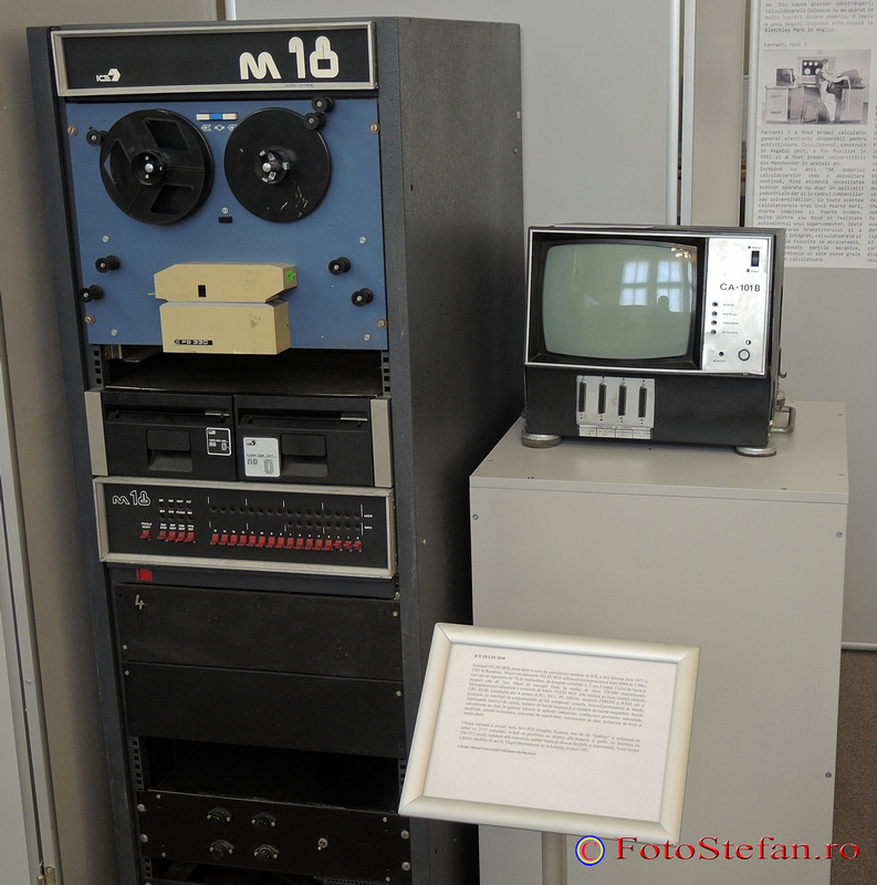
1. Mainframes behind the Iron Curtain
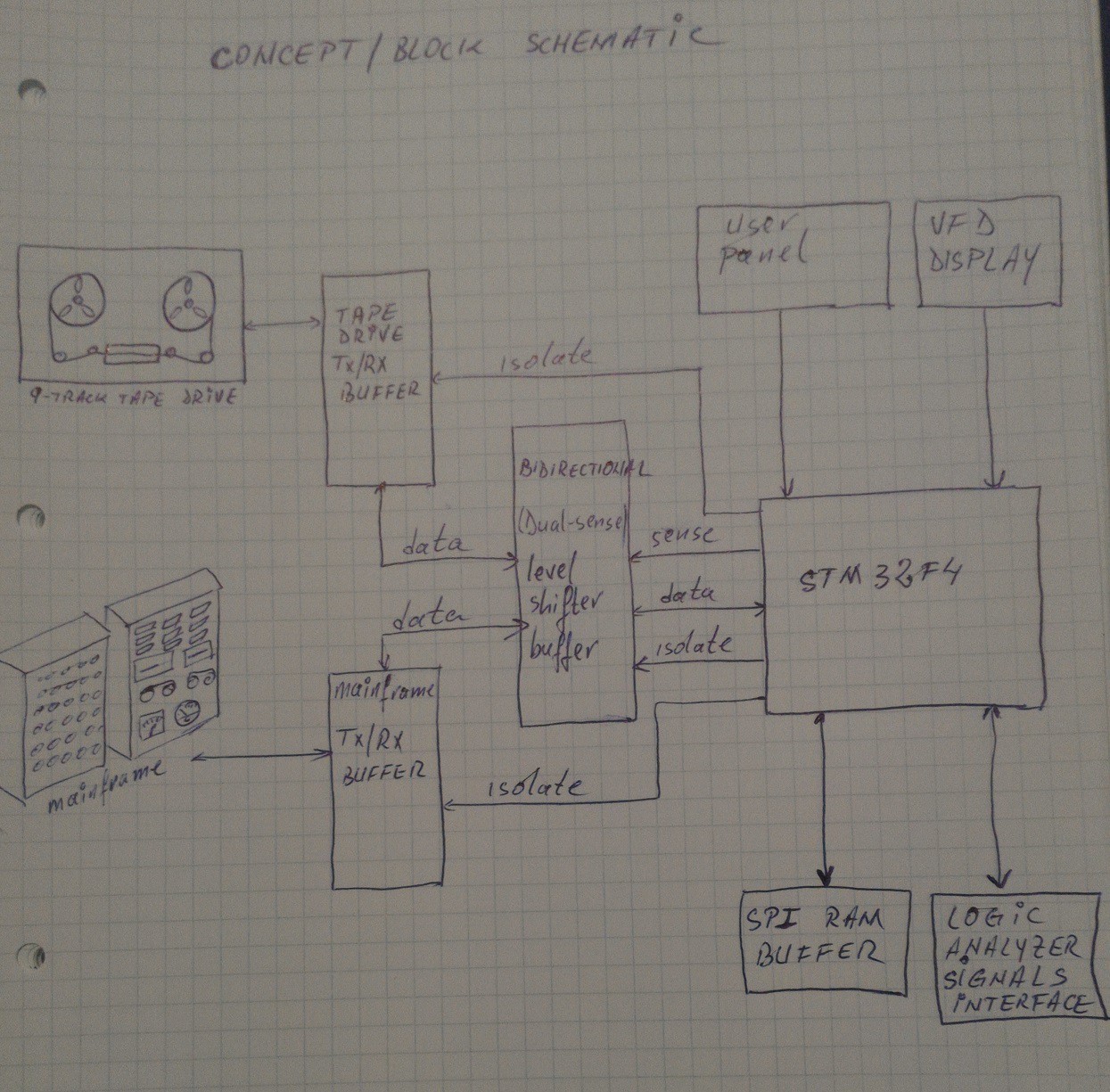
2. Concept design - schematics and discussion - short system description;
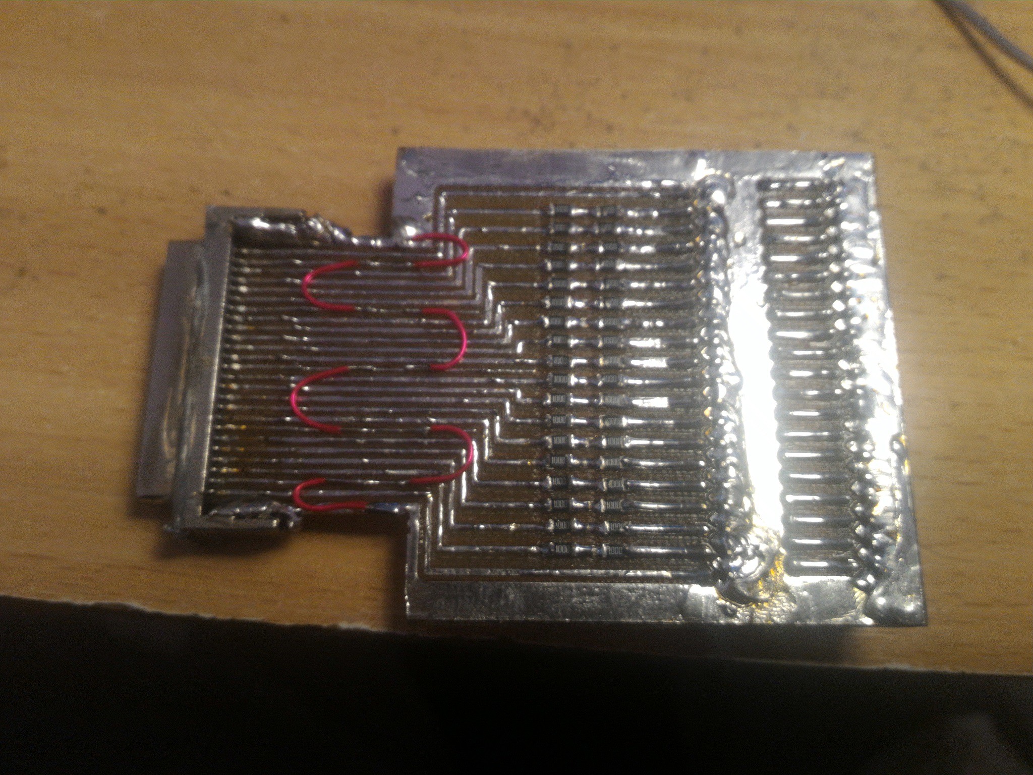
3. Pertec interface schematic - big pain for the eyes;
4. Arduino Mega 2560 central processing unit - prototype failure;
5. PCB - First prototype - failure;
6. Experimenting with VHS 1/2" tape (I) - 5 km (16404 ft) instead of 2600 ft! Cool!
7. Second prototype experimental schematics - don't try this at home, it's not final
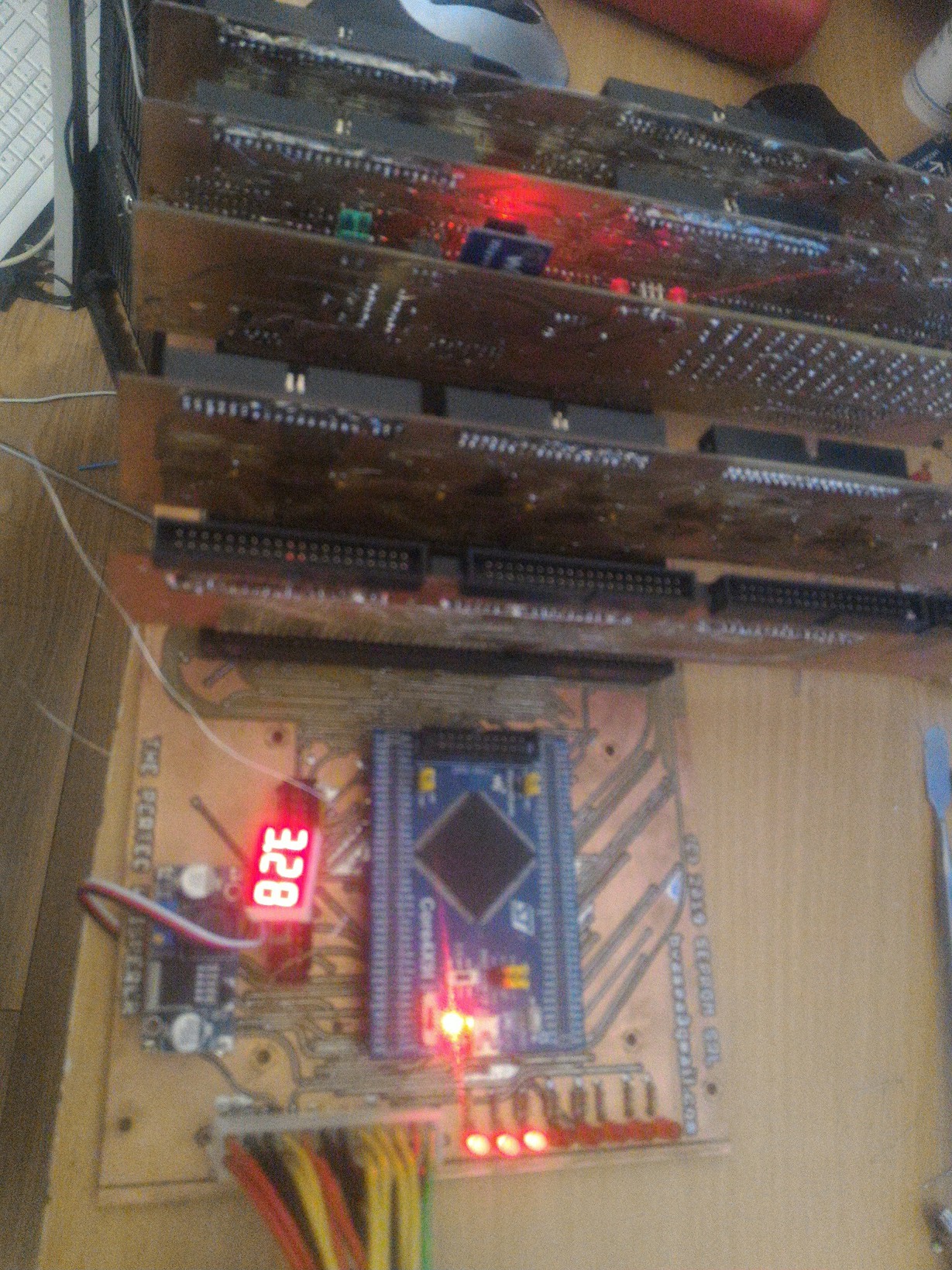
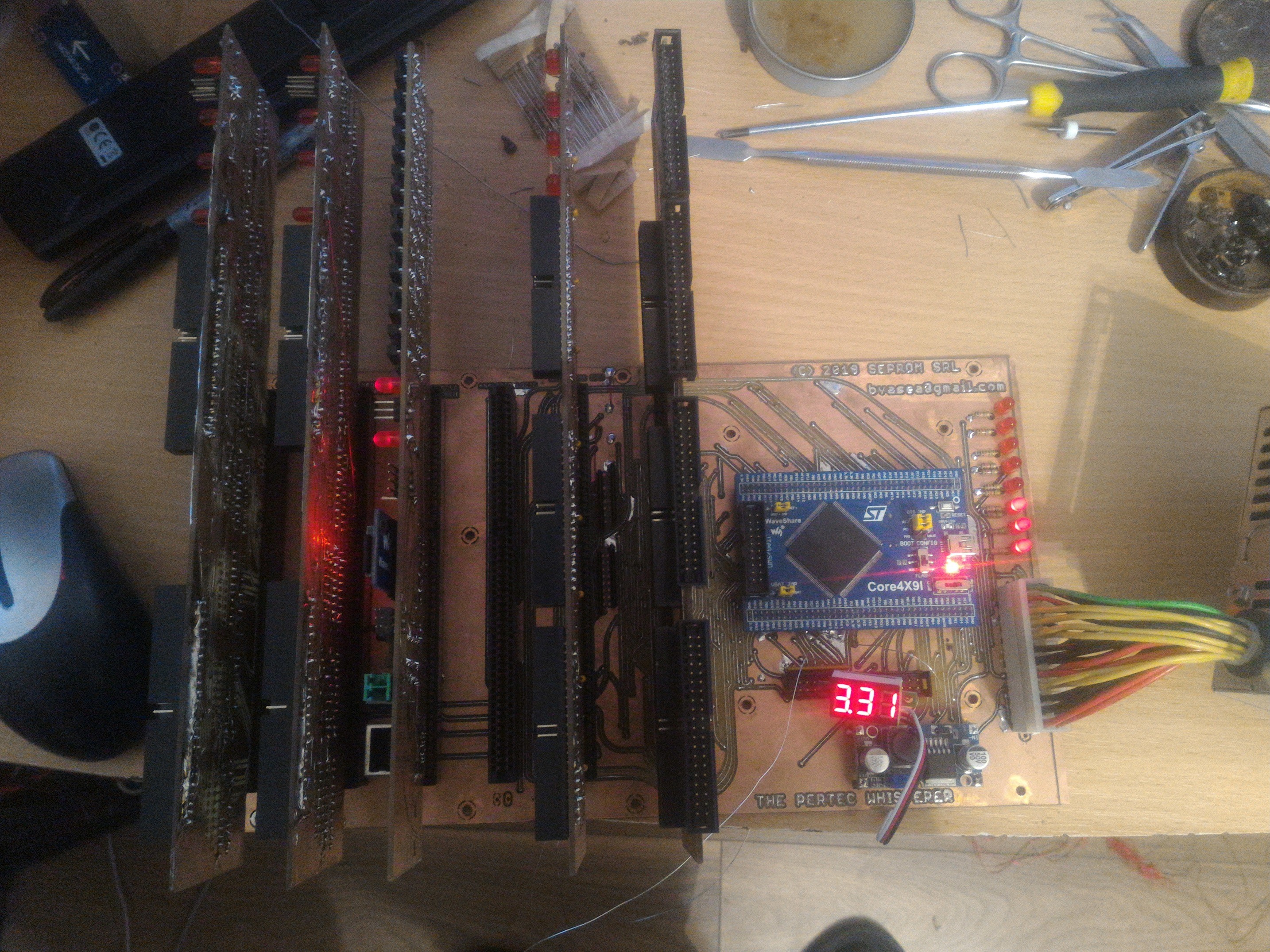
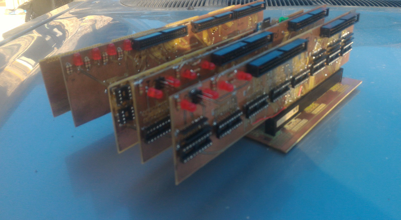
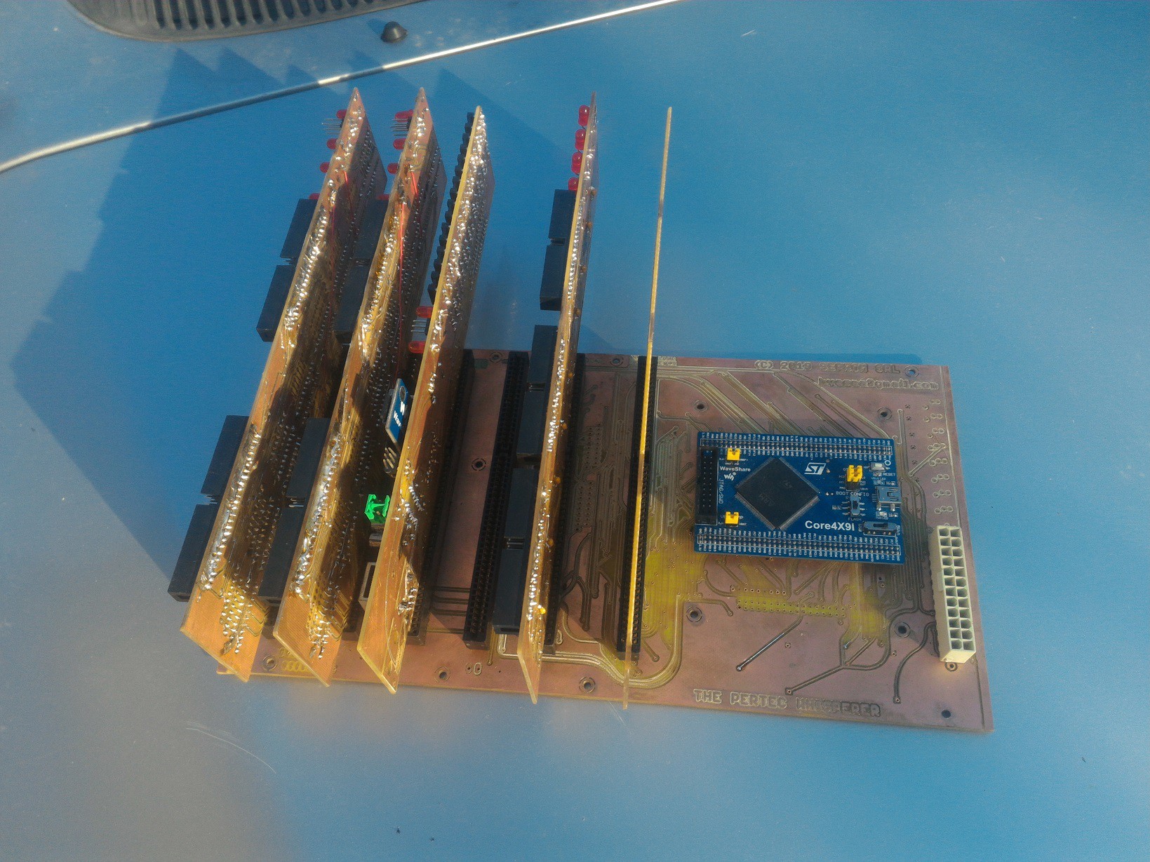
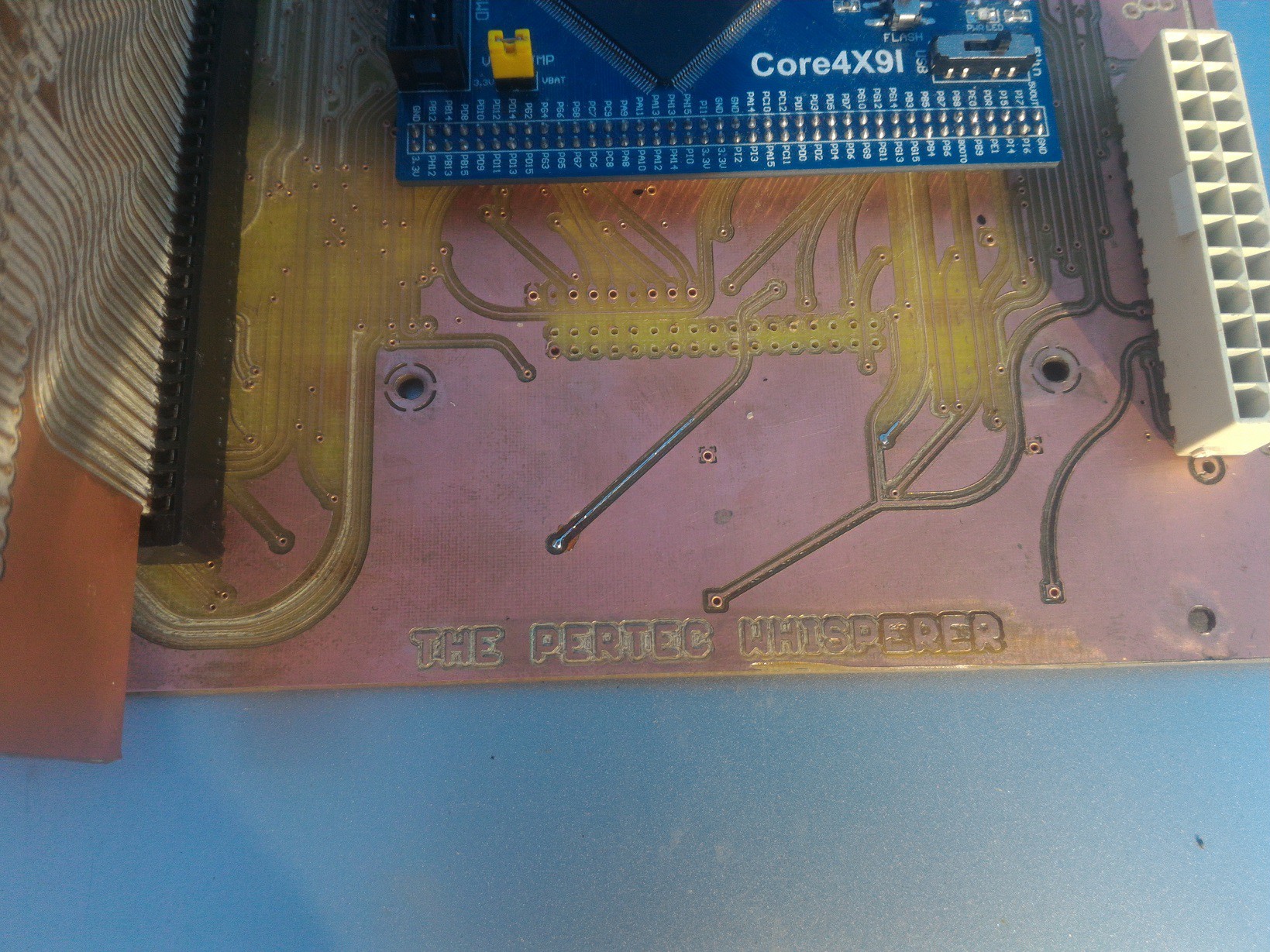
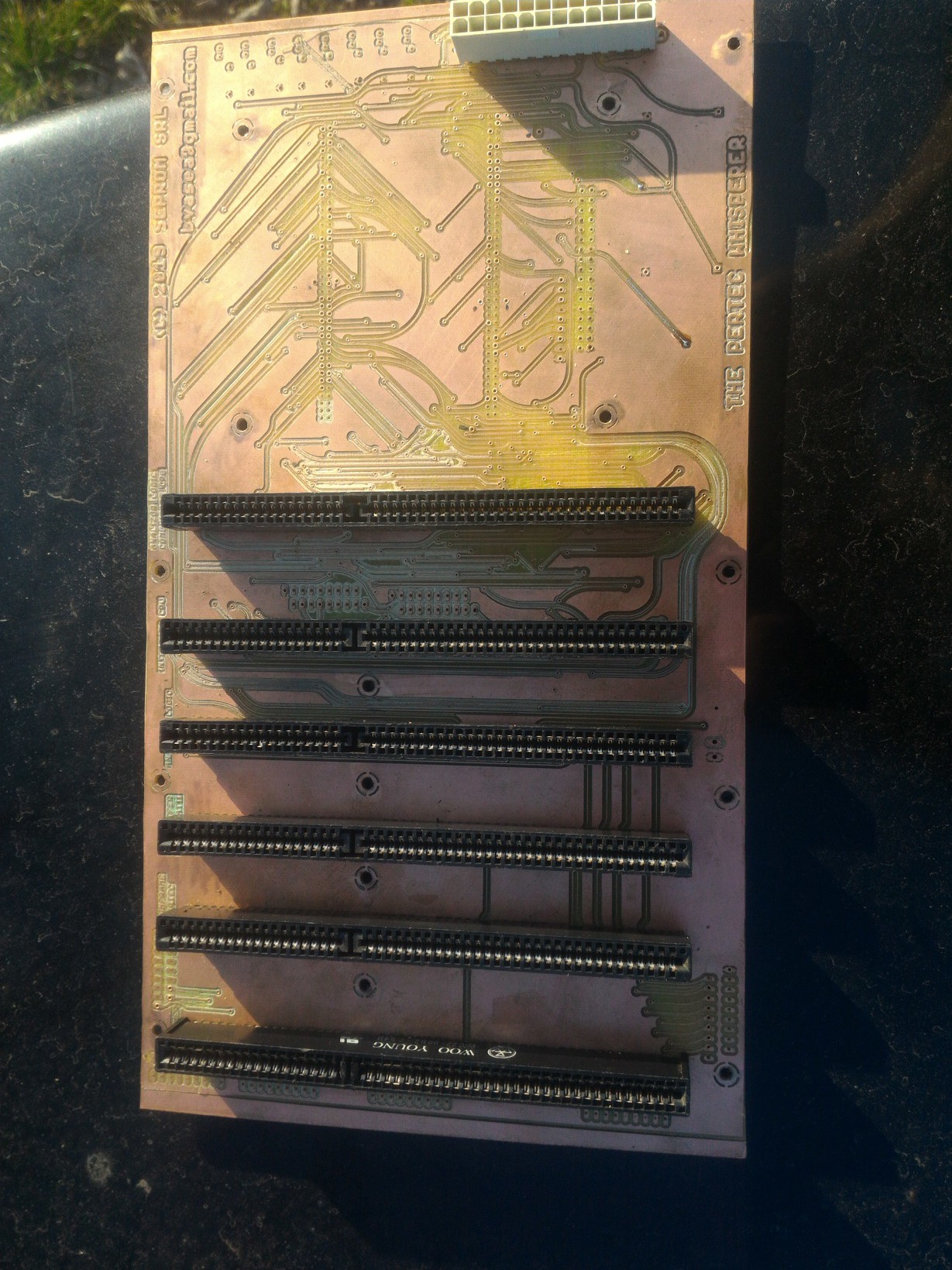
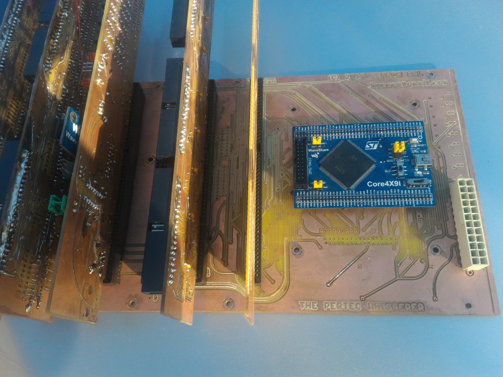
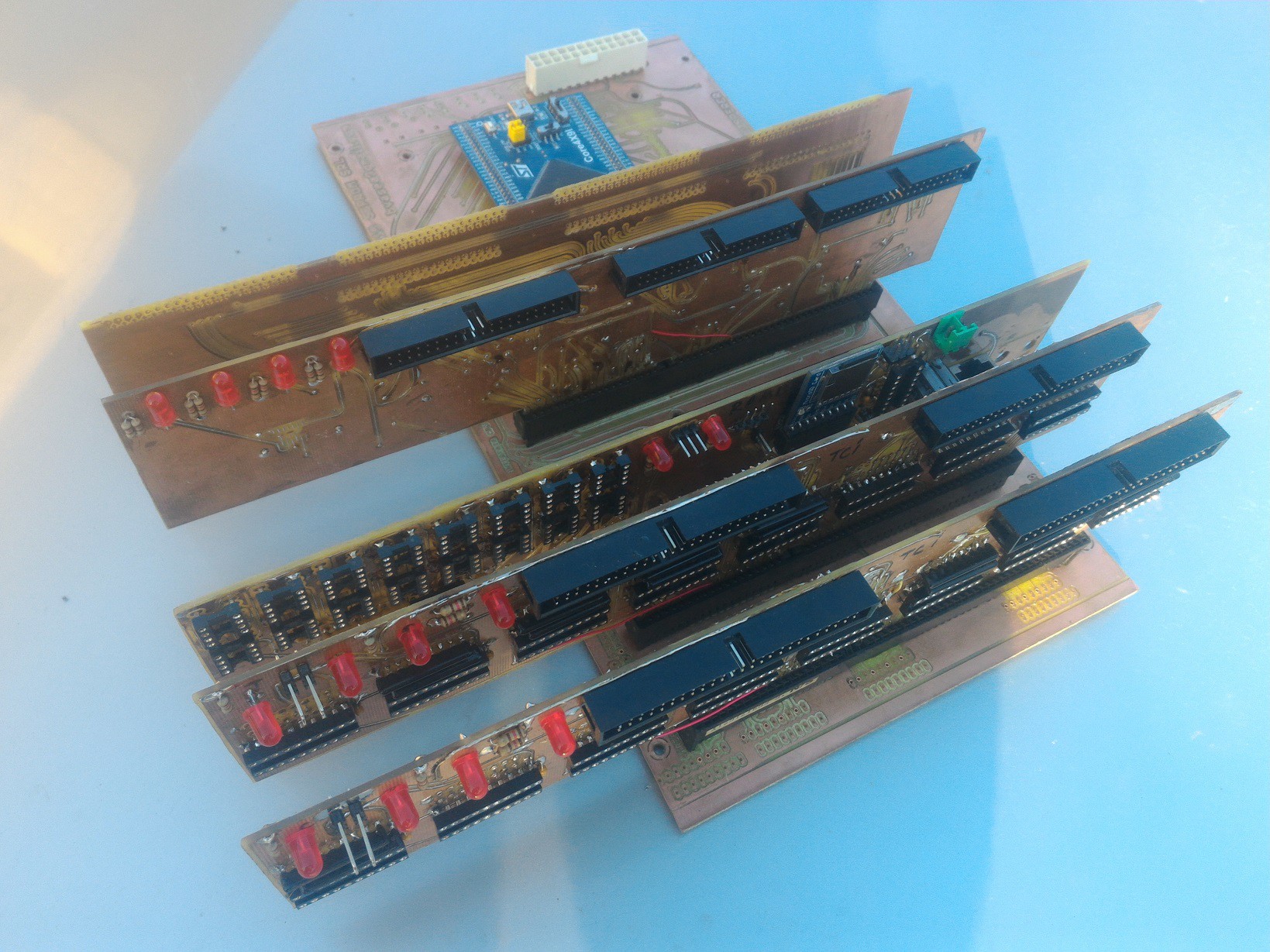
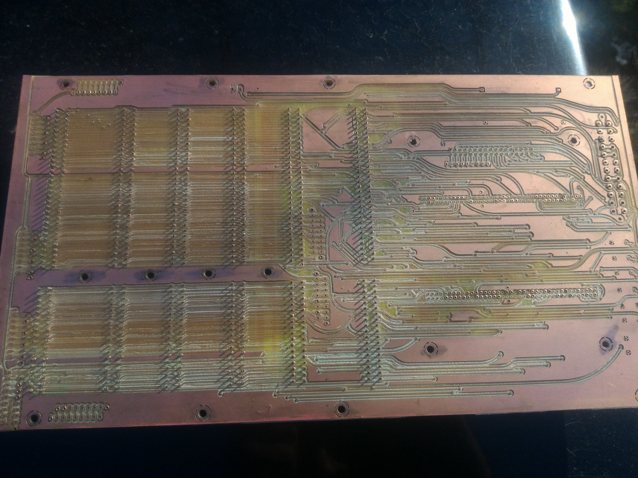
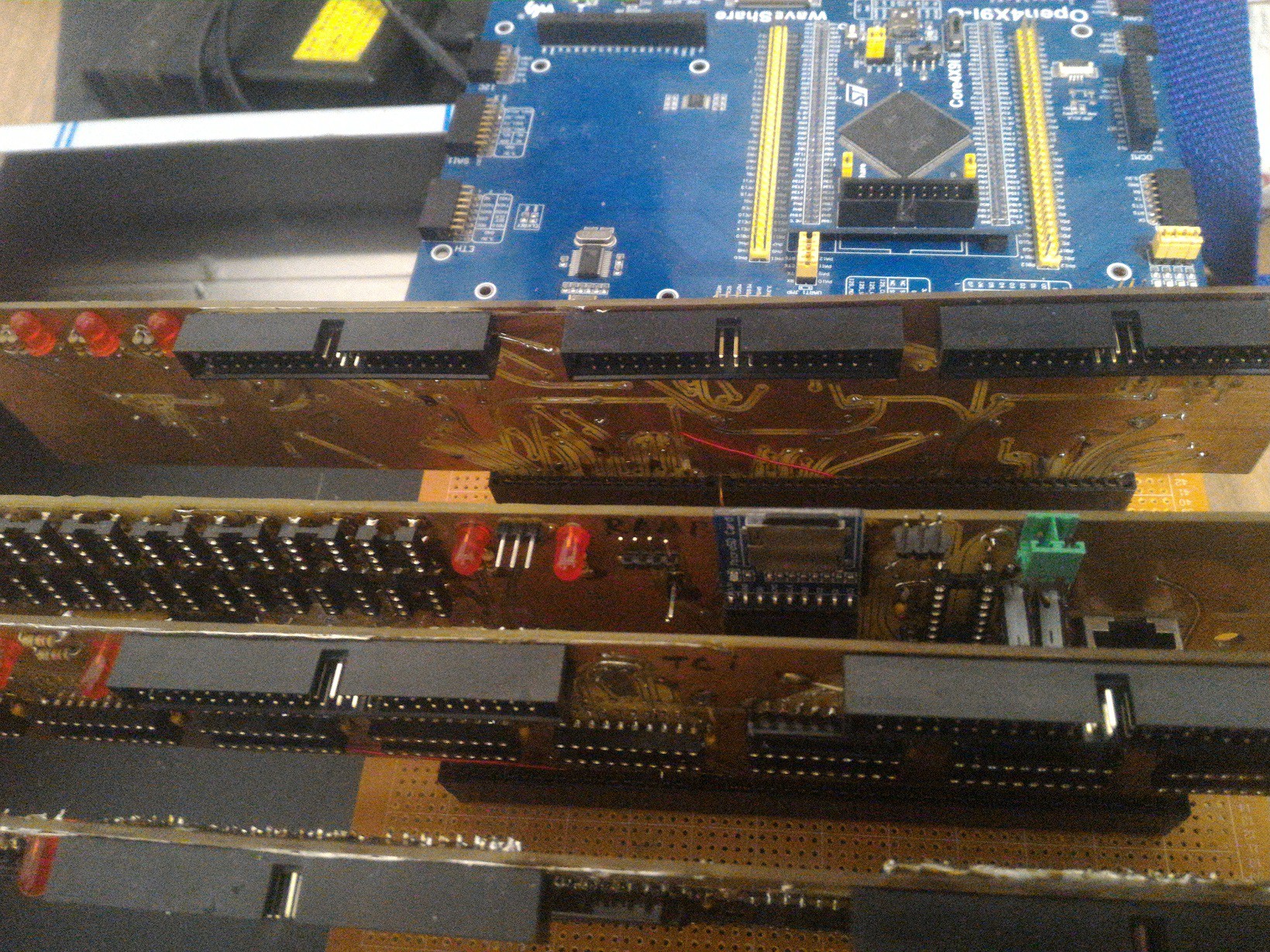
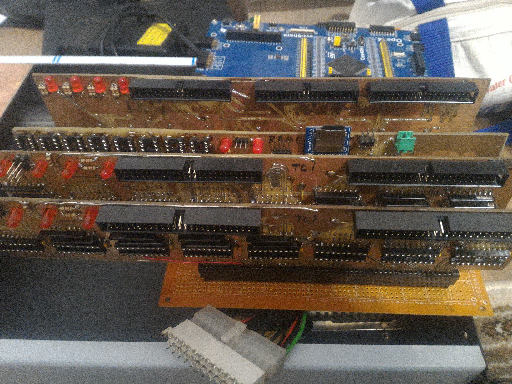
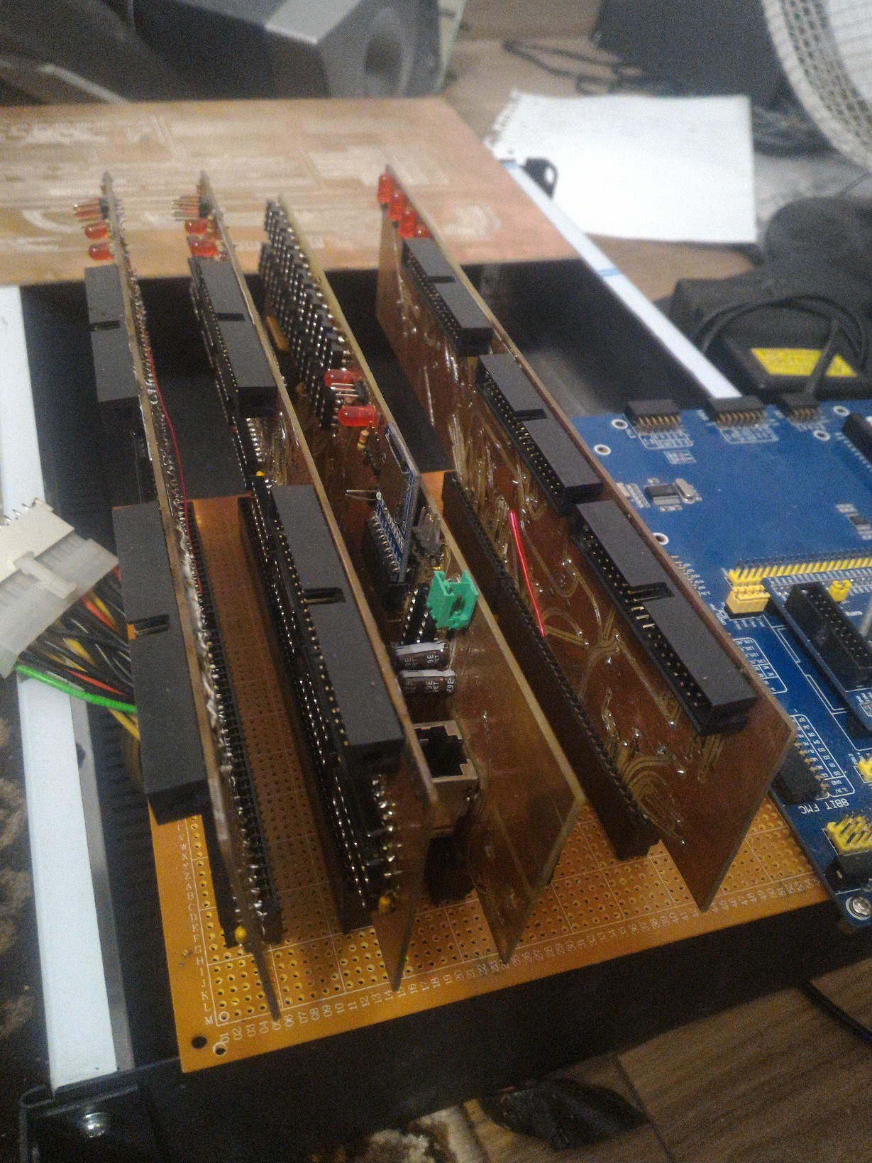
8. The motherboard (1) - the anticipation of many sleepless nights;
9. The motherboard (2) - this is for people who enjoy pain;
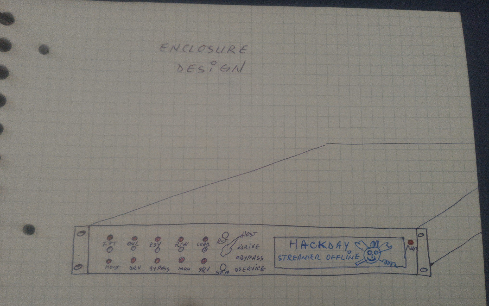
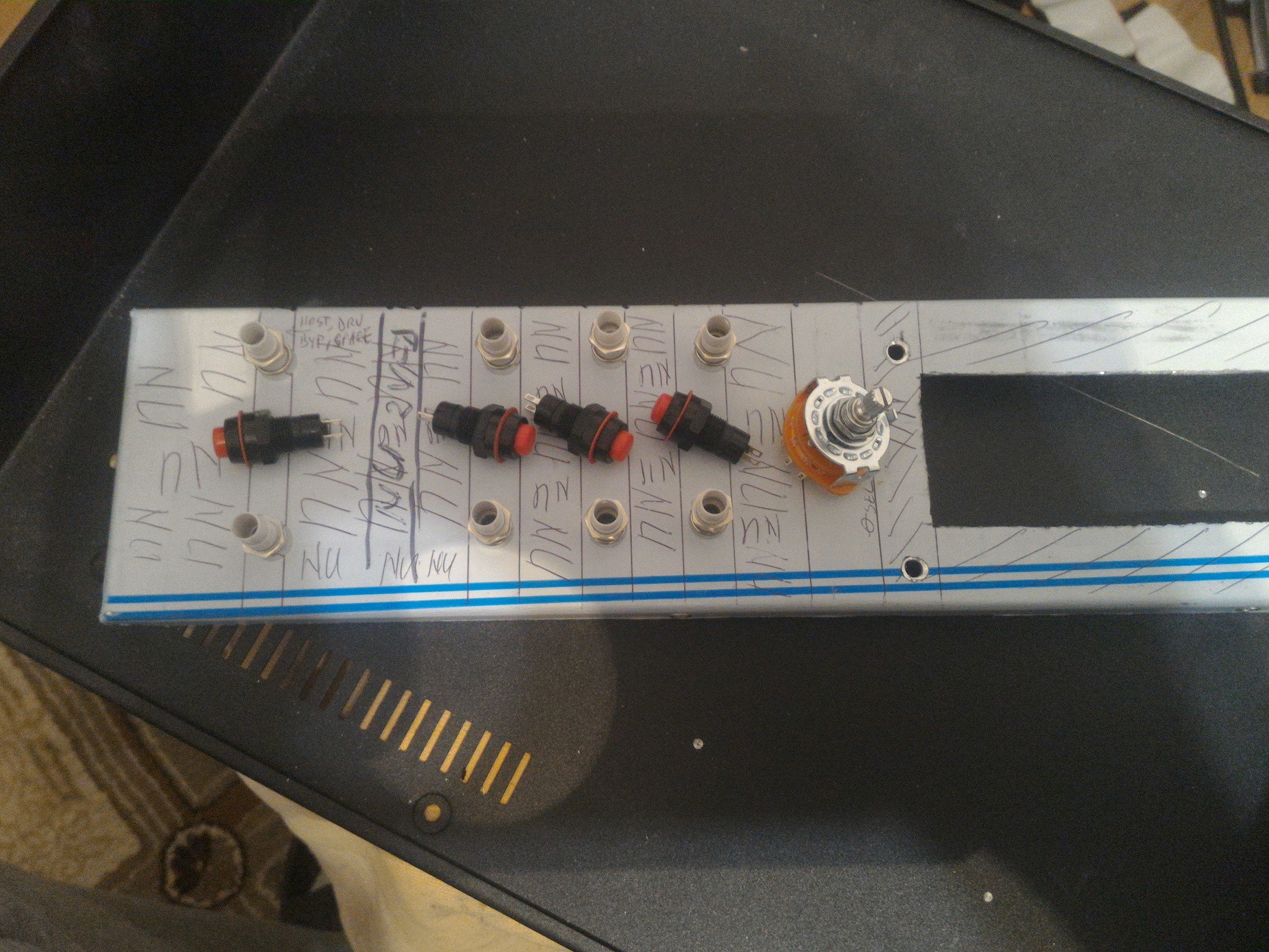
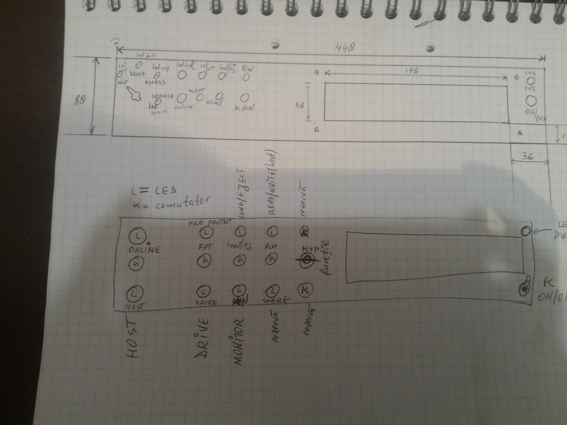
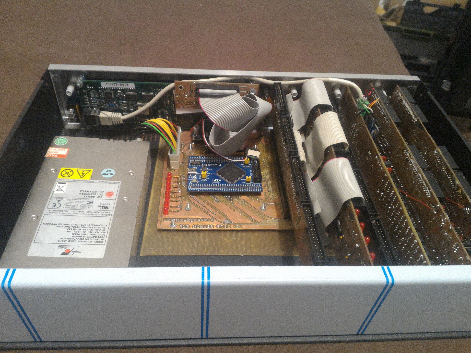
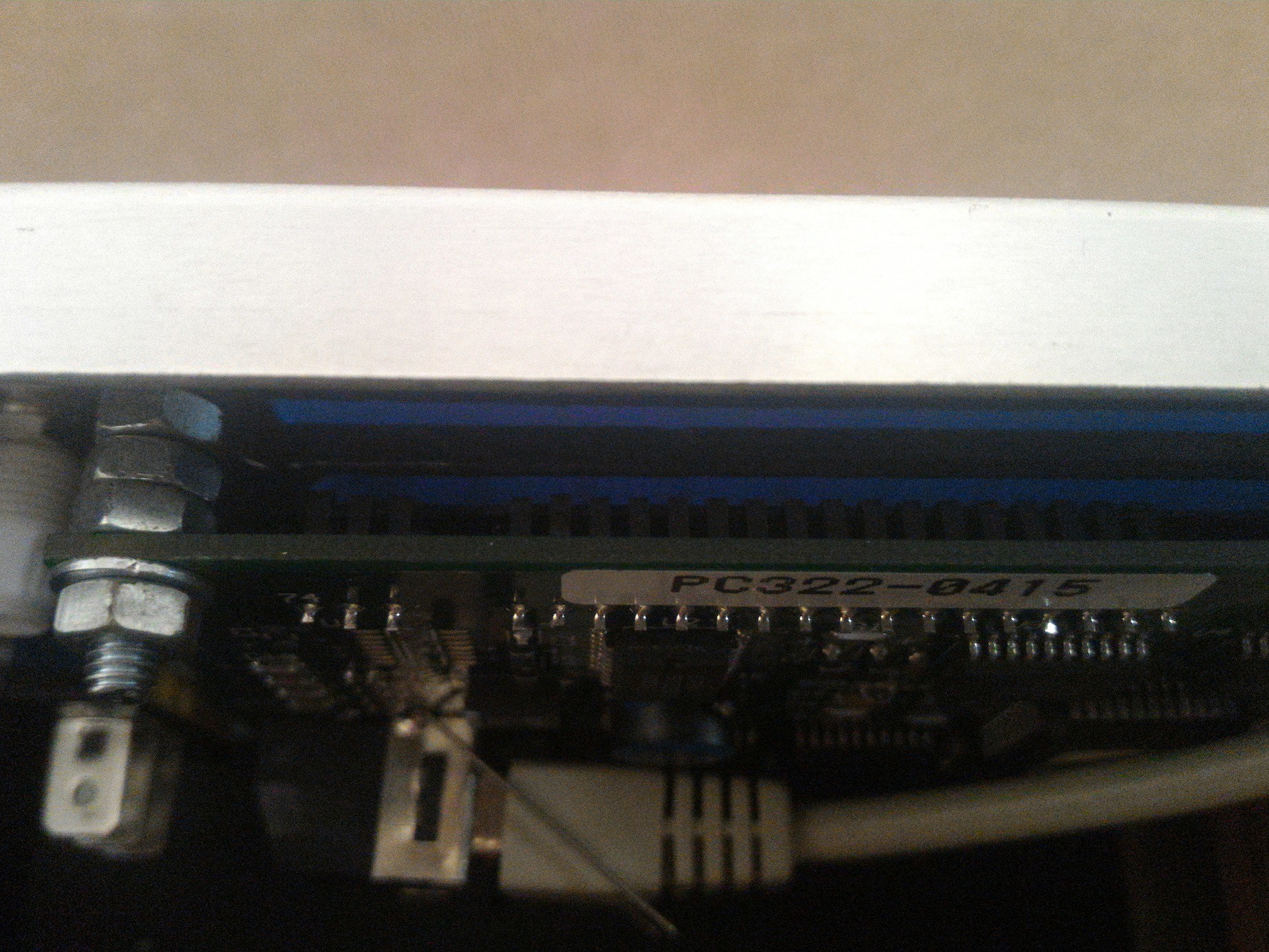
10. It's alive! ALIVE! - the magic is flowing;
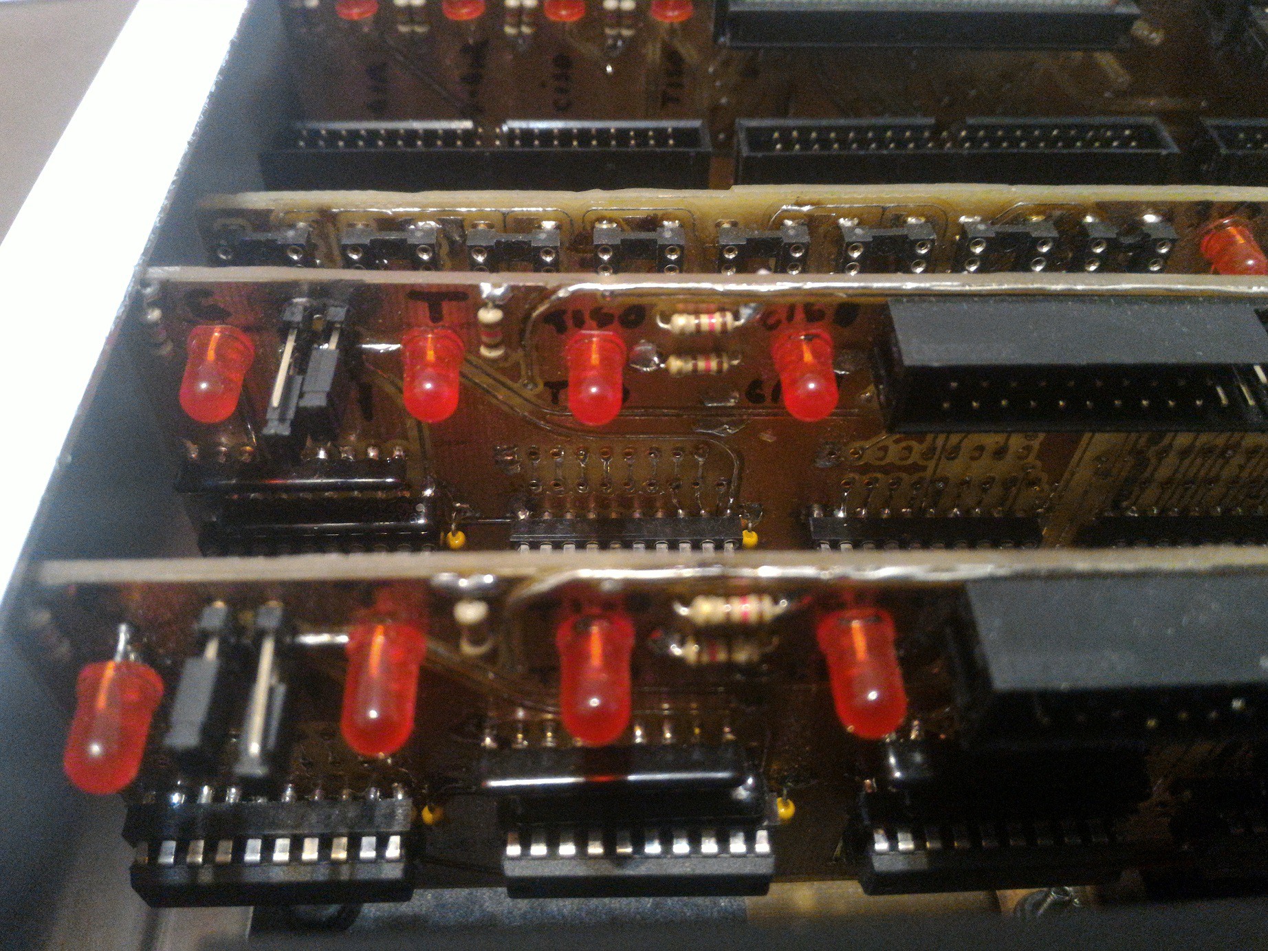
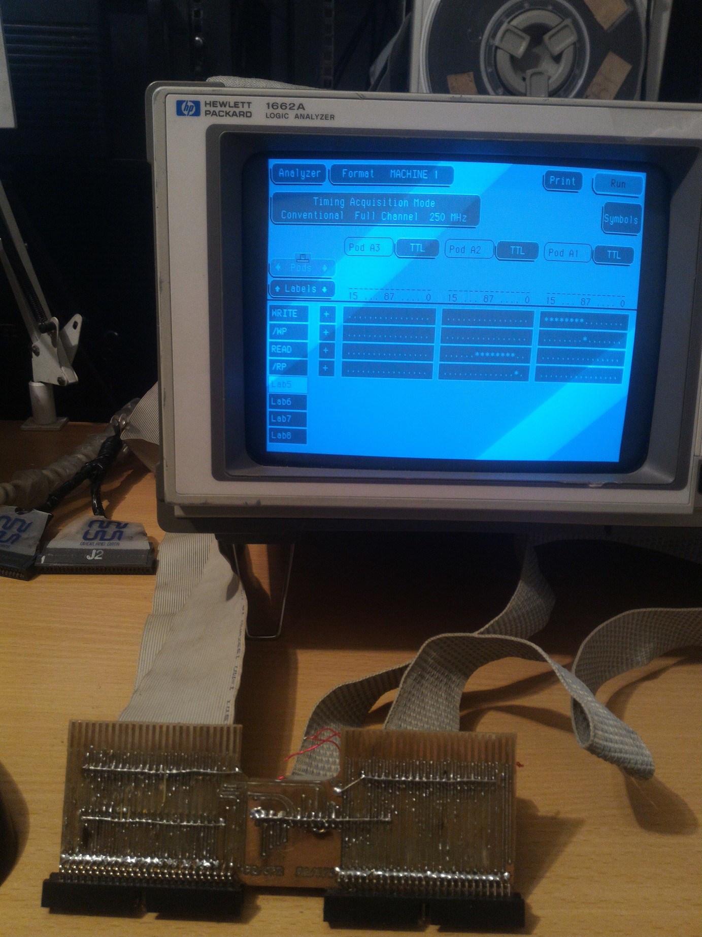
11. Jack in the Box - system installed inside a 4U rack-mounted enclosure and some experimental graphics using a HP1662 logic analyzer;
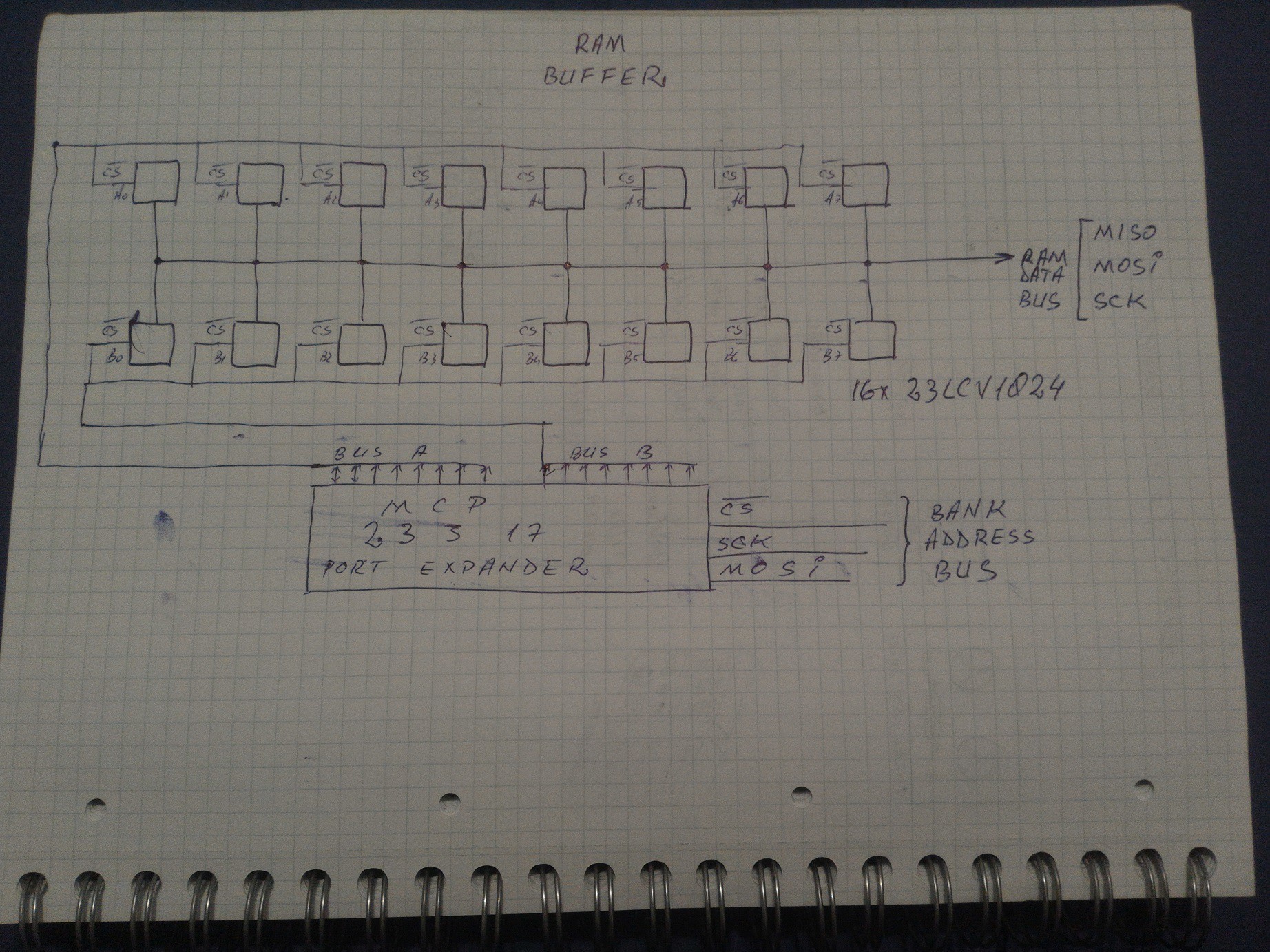
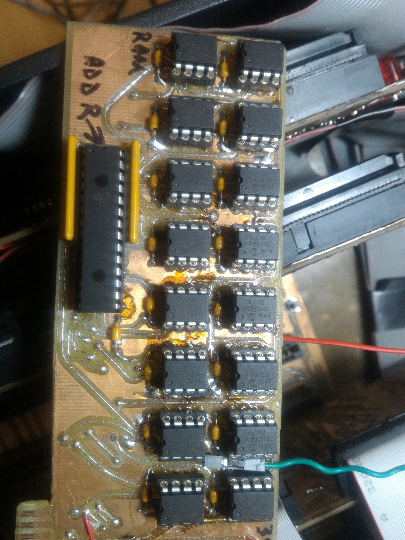
12. Pertec interface signals explained - some kind of ancient digital zoo;
13. The RAM Buffer and some software-related details. Bad luck, it took me a whole month to make rambuffer work as a big file;
14. Project published on Hackaday Blog - thank you.
15. Whispering in host mode - description of the internal tape image storage format modified after SIMH .TAP format;
Upcoming:
16. Work in progress - becoming "DRIVE": sending/receiving data to/from the mainframe. It is working. Still no good beer.
___________________________________________________________
Here are all the previous steps:
[2009] acquired a 9 track tape drive;
[2010] recovered a communist-era Digital Alpha Numeric Terminal vt100-compatible;
[2013] found an old mainframe and brought it home part by part. Also communist clone;
[2014] acquired the second tape drive - power supply broken;
[2018] Restoration project started
First step - getting the tape drive working.
This project aims to build an interface between modern and old tech. In order to get the monster working I need whatever data I can get: operating system, backup tapes, software, floppy disks, anything.
Industrial 9 track Tape Drives talk Pertec and this is the interface I am going to focus for now. So these are the functions:
1. PERTEC (9 track tape physical drive) to MicroSD Card (host microcontroller) converter - read/write data from/to tape;
2. PERTEC Drive Emulator (micro-controlled sd-card) to Mainframe (host) - acting as a genuine 9 track tape drive peripheral;
3. PERTEC (9 track tape physical drive) to SCSI (host) Converter - some people decide these devices should cost a ton of money and I want to have some fun by telling a little bit of their secrets;
4. 9 Track Tape-based USB Drive - a big, huge, mega useless mass storage USB.... wooden-stab or stick - just for fun.
My English is not too good due to the lack of good quality beer in my city, but you will get the idea:
In the mean time I'm getting my brain cooked at http://bitsavers.org/components/ while reading tons of documentation about anything related.
Project status: beta testing.
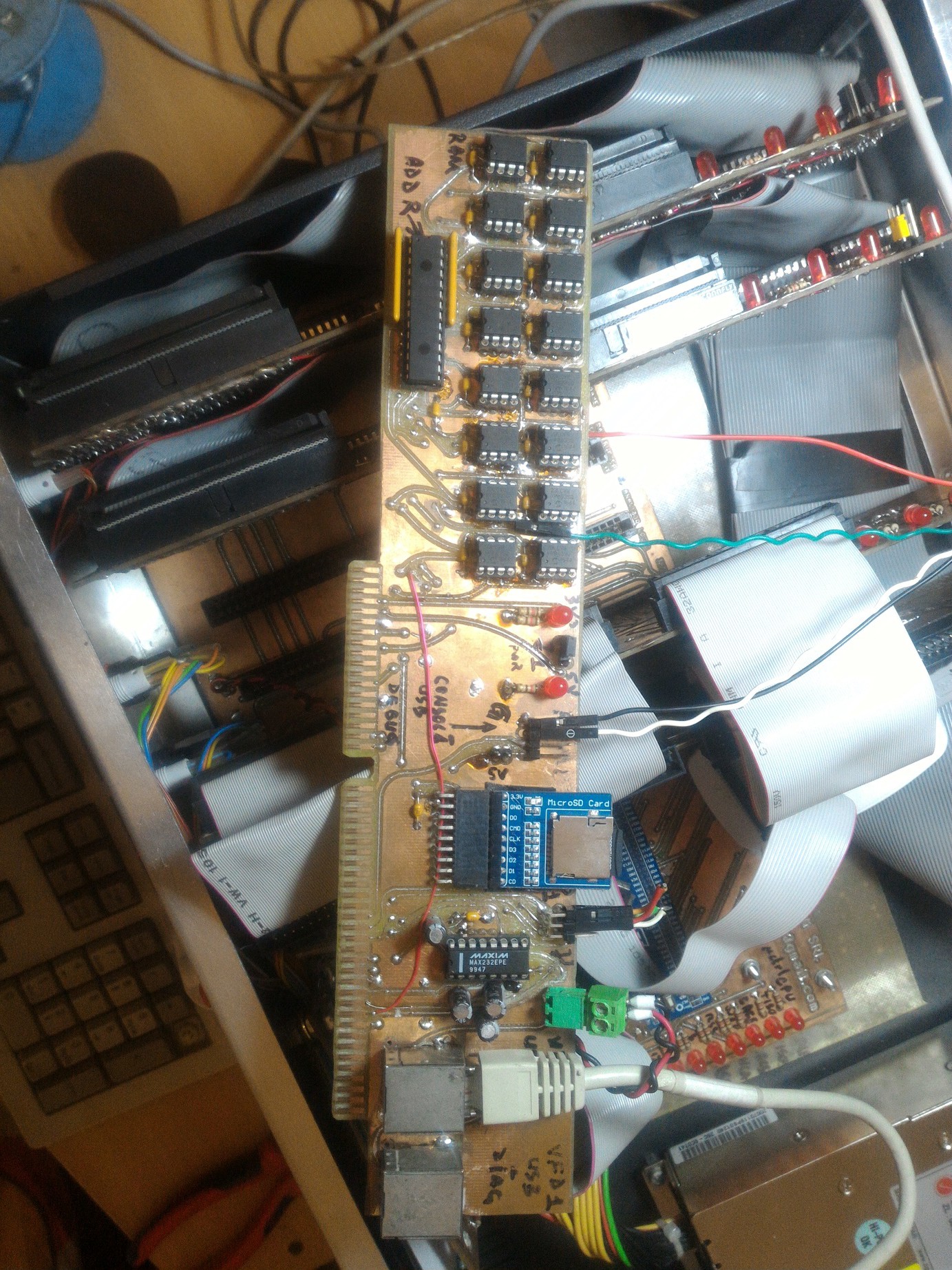
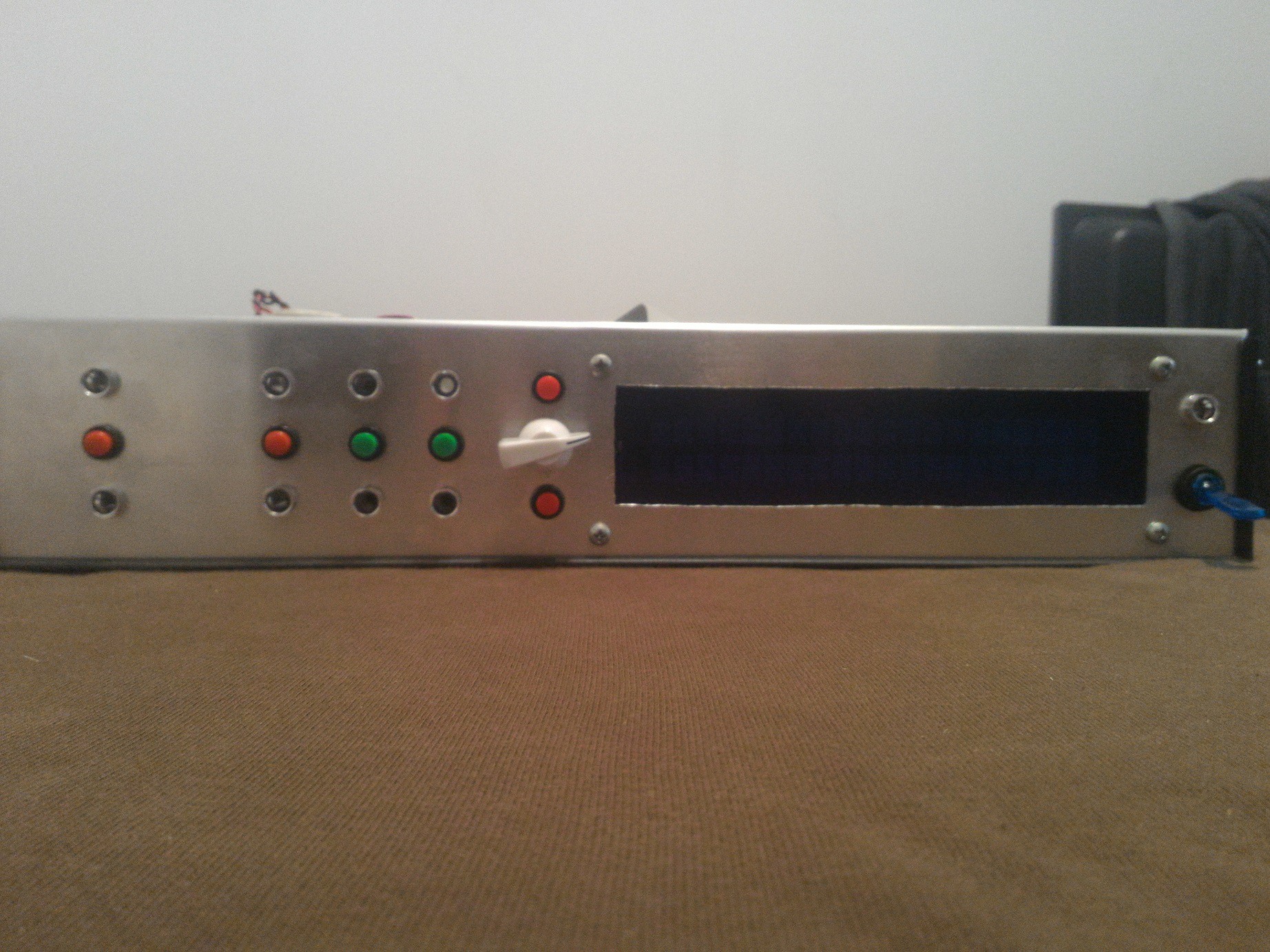
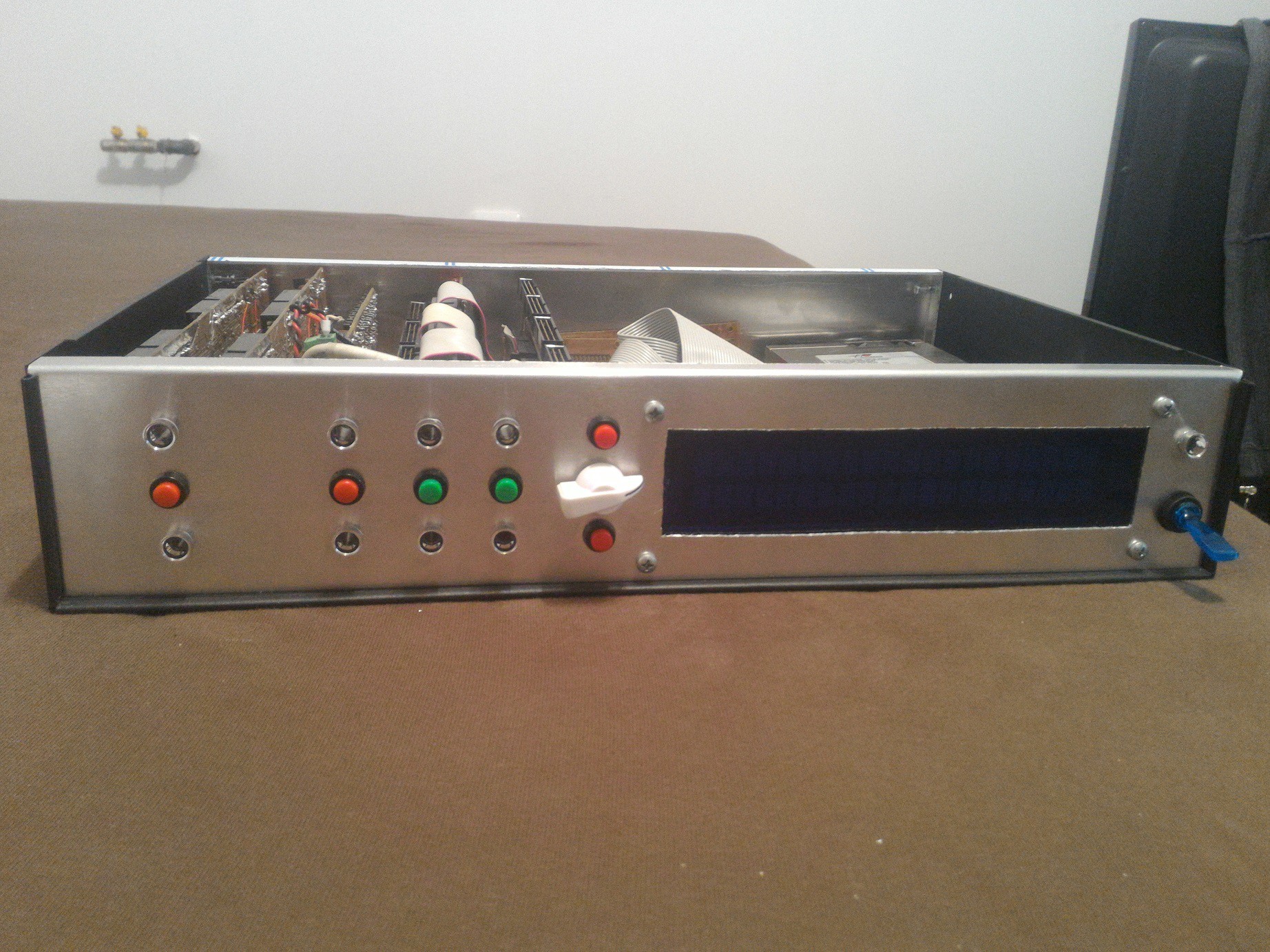

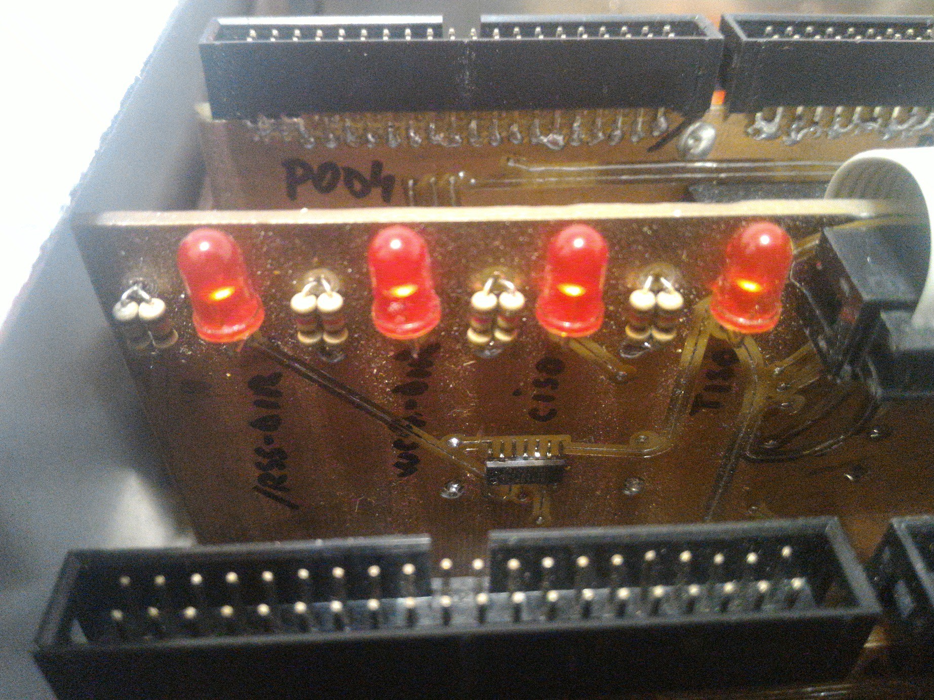
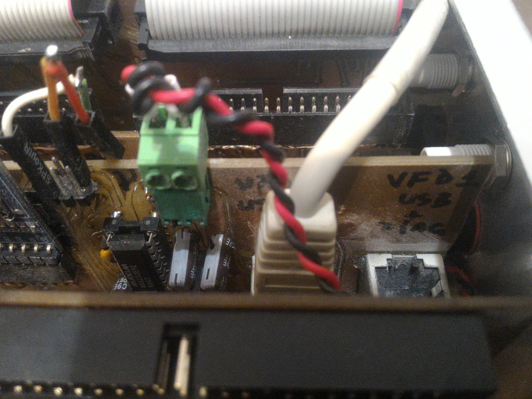
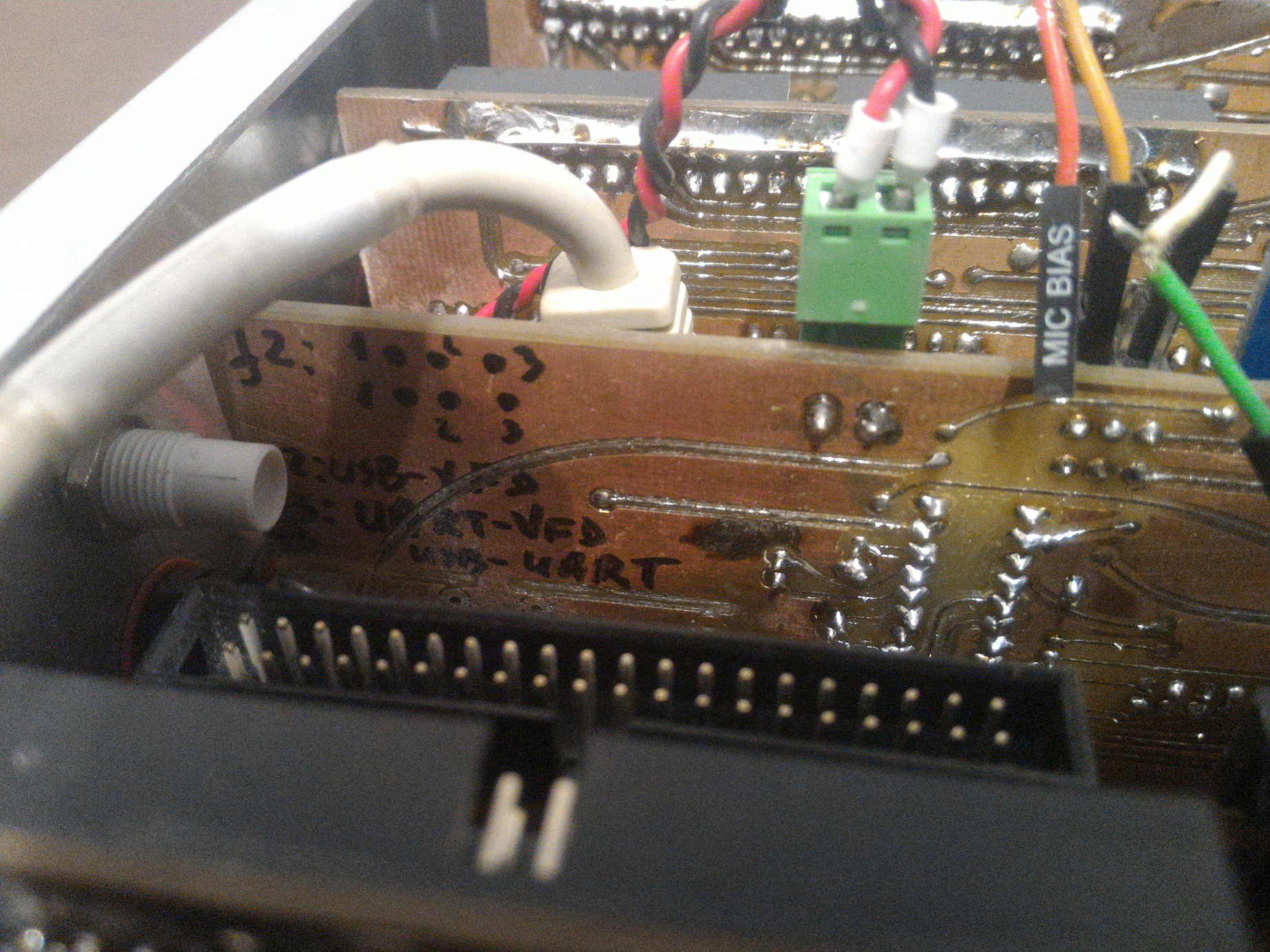
 Display via an old POS 2x20 VFD with 9600 baud serial line.
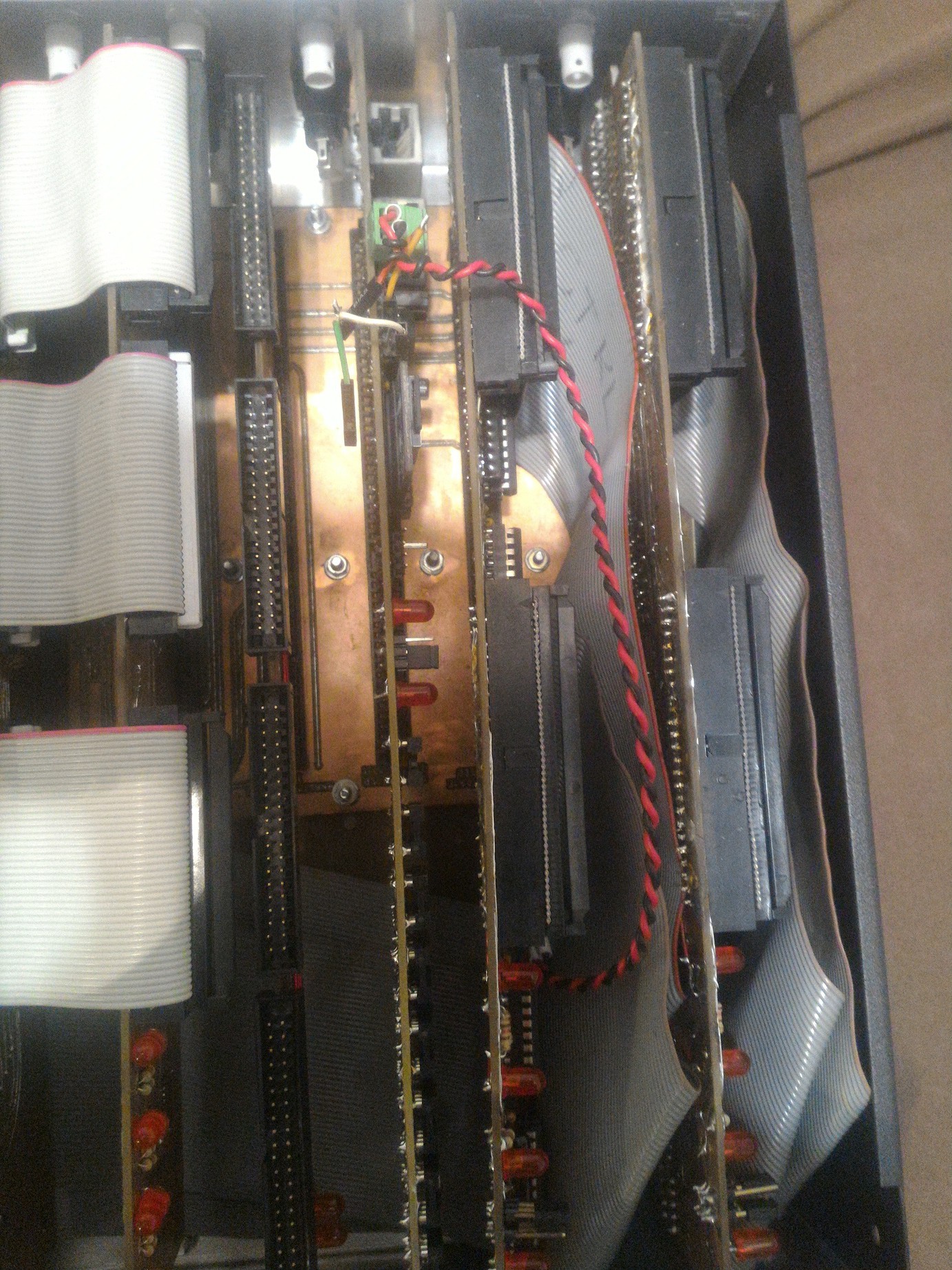


 Kaili Hill
 Mangus Tiranus
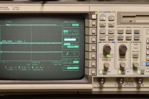
 Bharbour
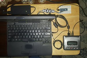
 Jac Goudsmit
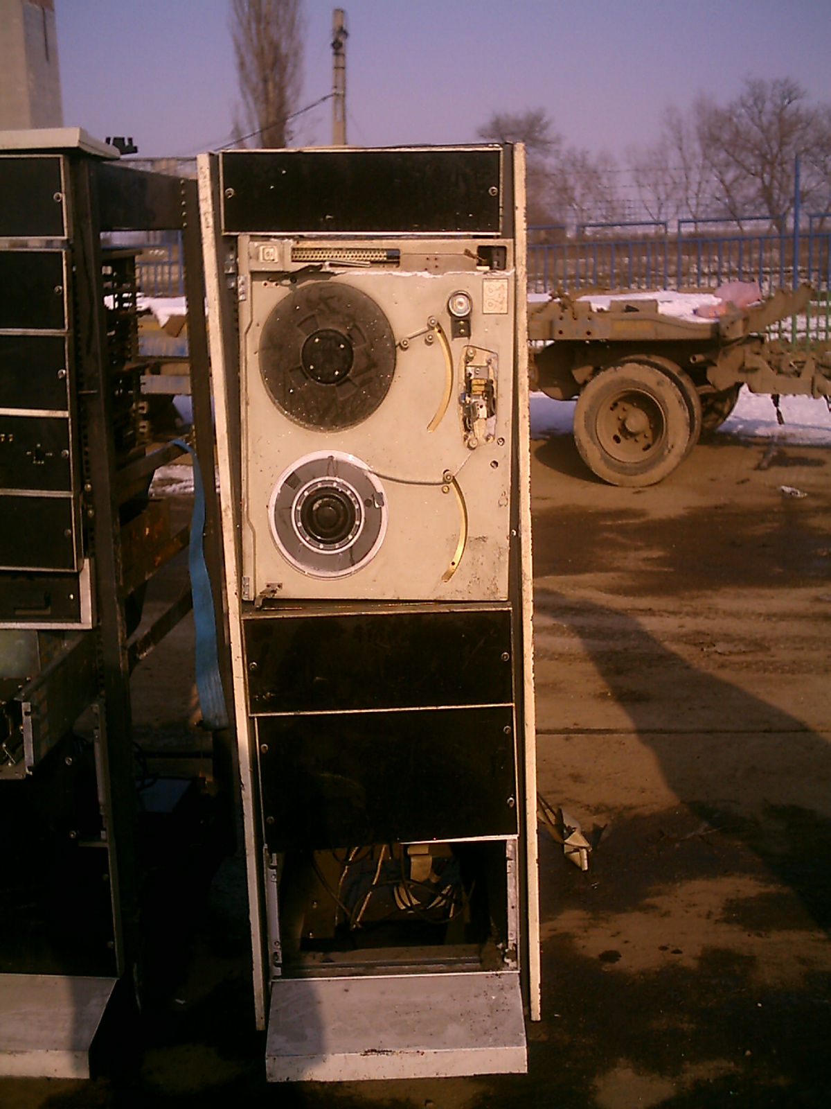
Wow, congratulations! 👏 Have a beer, good or not.