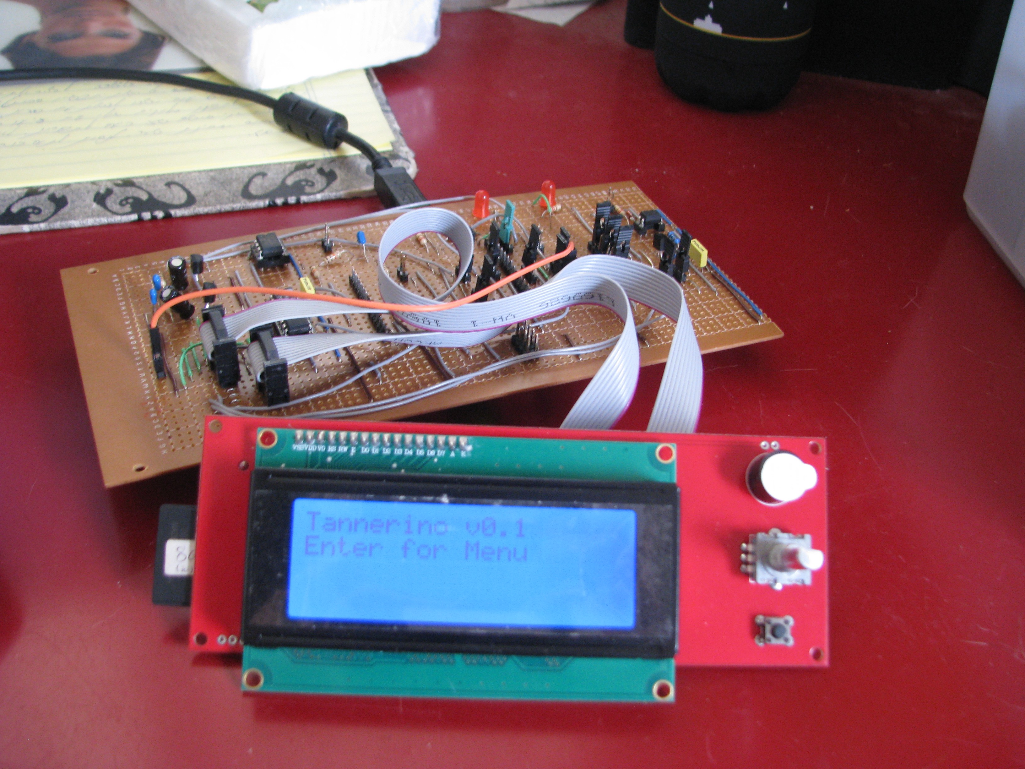
• So... what's my problem, anyway?

    uri.shani04/22/2018 at 22:00 0 comments

    As I wrote before, the Tannerino will be a slider MIDI controller for monophonic (or pseudo-polyphonic) tone generation. I plan on making the slider about 60 cm long, and make it produce continuous notes over up to 4 octaves. Initially, I thought of just providing a center note with a pitch-bend cc, as I found out that pitch-bend can provide up to 24 semitones up or down. This was also the reason I decided to go with an external 16 bit ADC, as the pitch-bend cc is also a 16 bit number. But, I found out later that most synthesizers can only do (+) or (-) 2 semitones. So, here's one problem I'm facing. The other problem I have in this design is the integration of a switch in the slider. In some of the versions of the original instrument, there was a switch located on the slider, which turned on the sound output of the oscillator. I thought of having a ribbon cable dangle from the slider, but that doesn't seem like a long-term solution, as it will probably just crack with material fatigue over time. Third problem, which came up while testing my initial firmware with a menu over an LCD, was with the tone generation. Without the LCD, the sound was continuous and (thanks to the nature of a clean sine wave) quite boring. But when I added the LCD, the sound was jittery and the sound was more like a cricket. So, to recap, I have three design problems / goals:

    1. Make the MIDI output a continuous one when gliding through different notes.
    2. Find a way to have a mechanical switch, actuated by the player while sliding through notes, and placed on the slider itself.
    3. Get a consistent sound output going while still having a menu based UI, as well as MIDI generation.

    So, solving the first problem will, I suppose, require some interpolation of the current location of the slider, and sending a MIDI note with relative pitch-bend cc.

    The next problem is more of a mechanical problem. I thought of maybe having a T-shaped bracket with contacts on both sides, but that still requires some investigation.

    The third problem (which is probably far from being last), requires some investigation into what actually happens when the note is played. I got a kit oscilloscope with the boards I designed for my other project, and hopefully I can figure out what's up with that once I get the scope going. 

  • Test board & ideation

    uri.shani04/20/2018 at 09:29 0 comments

    The idea for my other project (Arduino Blocks for MIDI Controllers) stemmed from needing a menu based display UI for the Tannerino.  I wanted to be able to set different wave shapes, range and tunings - and thought the RepRapDiscount Smart Controller was just the right tool for the job, since it includes a 2004 LCD character display with an on-board rotary encoder. That seemed like the right, uncluttered UI approach I was looking for. But since I don't have much of a background in either EE or software, it took me on a bit of a journey trying to get everything I wanted to work.

    Anyway, as I'm about to receive the PCBs and components I ordered for the AB4MIDICtrlrs, I got going in fitting the right components for getting the job done. The stripboard above acts as an Arduino shield, and contains the main functional blocks for the Tannerino:

    • A breakout for the Smart Controller (using '595 for the display).
    • A transistor + RC filter for the synth output.
    • A digital potentiometer for volume control.
    • A MIDI breakout w/optocoupler.
    • ICSP  header of the Atmega16u2 on the Uno R3 are broken out for jumpering - important for working with mocoLUFA.
    • An additional SPI header is broken out for getting to the additional 16-bit ADC.

    Even though it's a bit different in design from working with the AB4MIDICtrlrs UI shield, I've already done this version a few months ago, and I can use it to at least get the libraries I need going.

    I hope to get the software side going before PCBs arrive. I will probably feature the libraries in my other project page as they are more general, and reserve this page for more specific details.

  • Mechanical parts overview

    uri.shani04/13/2018 at 12:22 0 comments

    Just to get going - a short explanation of the mechanical components I laid out in the project photo:

    • A manual slider (either 3D printed or carved out of wood) will contain a micro-switch.
    • The slider will be actuated by hand, and guided on a round 600x8mm linear rail such as used in 3D printers by the 8mm bushings seen middle-right.
    • Micro-switch will close a circuit by the slider touching two strips of copper tape (top center).
    • The bead chain (top-left) will transmit movement from a slider onto a 3D printed pulley.
    • 3D printed pulley (yet to be printed) will be mounted on a D-shaft (center).
    • D-shaft will be mounted through two lipped ball-bearings (second from top, both left and right) in Actobotics U-bracket (top-right).
    • Flex-coupler will transmit rotation of D-shaft to 10xRotation potentiometer.
    • Position of the pot will be read by the 16-bit ADC.

    I really hope to get the UI shield from my other project here by next week, and getting going again with this project by placing the 8-bit synth output components on a prototyping shield.