 Tim Wilkinson
I want each joint to be entirely independent, not only with the physical design but also the control electronics. I decided I'd build each with it's own Arduino board attached. I picked Arduino because they're easy to work with, I have all the tools, and atmega328p's are very cheap. The board also needs to monitor the position of the joint and move it according to an external input. I also use a simple, single chip, h-bridge motor controller. With one decoupling capacitor and a pull up resistor (why the atmega328p doesn't have internal pull up on RESET I don't know) this was the minimum component count I could get away with (the Arduino runs on its internal clock, avoiding the need for a crystal).
To sense the position of the motor I tried a few things. I though I could count the rotations of the worm gear to work out where the nut would be; but I dislike this because it assumed I know where the nut starts and somehow don't miscount - I'm always working with relative positions which is error prone. Next I looked at using flex sensors, but these are rather bulky compared to the size of the joint and also quite expensive. A slightly different approach to measuring the joint "bend" was to try a conductive elastic which changes resistance when stretched. Unfortunately the only source I could find supplied rather thick elastic, and its not that stretchy when used in the very shorts lengths I needed.
The current solution uses Hall Effect sensors, mounted on the back of the PCB, to detect the position of a magnet mounted in the nut. As the nut moves up and down, the sensors detect where it is. The current iteration (PCB v1.1) uses two of these - one at the top of the PCB, one at the bottom. I had hoped to triangulate the position of the magnet based on the sensors readings. In practice the magnet appears to be too small for this to be reliable. I could only determine with certain if the magnet was directly above the sensor - anything else was easily effect by any other magnet that happened to be near by .... such as those in the motor. For now this means the joint can only move between two positions. PCB v1.2 has 5 sensors, which will give me 5 positions. I need to experiment with the new boards, but it may be possible to determine half steps (magnet between two sensors) with sufficient accuracy to give me 9 positions.
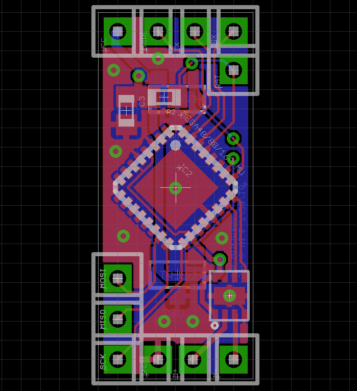
The final board has a number of connection points; some for power, some for the motor, and some for control. It also has a few points necessary to program it from the Arduino IDE. Of course these points are all non-standard and so I had to build a custom jig.
The finally board measures only 8mm by 19mm and fixes neatly on the side of the joint.
Discussions
Become a Hackaday.io Member
Create an account to leave a comment. Already have an account? Log In.